
Abstract
In this study, our goal is to create a surgical navigation system that takes stable measurements of a surgical area using RGB/depth cameras without obstructions, such as the surgeon’s head or hands. We mounted three cutting-edge D435 Intel RealSense Depth Cameras onto a ring and photographed the surgical area from three directions. We also installed a robotic mechanical system that can move the camera ring up and down so that the surgery can proceed smoothly. First, we calibrated the coordinate systems so that the coordinate systems of the three cameras (three-dimensional XYZ coordinate system) align and their Y-axis (vertical axis) aligns with the moving axis of the robot slider. Next, we captured an ArUco marker with each camera and visualized its position within the camera coordinate system. After verifying that the initial positions of the ArUco marker captured by the three cameras match, we moved the robot slider up by 50 mm thrice and investigated the degree of change in the measured position of the ArUco marker measured by the three cameras. The results show that as the ArUco marker moves farther away, the extent of error in the measured position of the ArUco marker increases. Additionally, the measured position of all the ArUco markers varied owing to the digital pixel error in the two-dimensional images (the pixel in which the ArUco marker is visible moves between neighboring pixels). Future work includes checking that the calibration pattern and ArUco marker are parallel to the camera ring and perpendicular to the robot slider using a level instrument; packing the calibration pattern and ArUco marker horizontally with vinyl; and implementing a moving average in the program to reduce pixel digital error in the calculations to sub-pixel level.
You have full access to this open access chapter, Download conference paper PDF
Keywords
- Neurosurgery
- Navigation system
- Intel RealSense Depth Camera D435
- Organ deformation and movement
- Brain shift
1 Introduction
In recent years, we have constructing surgical navigation systems for brain, kidney, liver and so on. There are many navigation systems in the field of orthopedic surgery because bones have few variations. In addition, we have a lot of navigation systems for neurosurgery and otolaryngology [1, 2]. These include endoscopic and/or lap-aroscopic surgery systems [3, 4] and robot surgery systems [5].
We have supported doctors by designing a sensor-based surgical operation navigator for brain, kidney, liver and so on [6,7,8,9,10,11,12,13]. For these, it was essential to accurately measure the surgical area with a depth camera to obtain a depth image. To accomplish this, last year we built a new surgical area-measuring robot-mechanical system and assessed the correlation between the distance the robot traveled and the change in distance of the depth image [14,15,16,17].
In neurosurgery, doctors create surgery plans in conferences held beforehand based on DICOM images from CT/MRI captured before the surgery. Doctors use the DICOM images for neuronavigation during brain surgery to ensure that brain tumors are accurately removed by the scalpel. However, cerebrospinal fluid may drain from the brain or its surroundings during the surgery, which can cause displacement or deformation of the brain. This is referred to as brain shift. Therefore, there may be some displacement between the brain in the preoperative DICOM image and the intraoperative actual brain for both the interior and the exterior. This could result in failure to completely remove the tumor, even if the surgery is performed according to the navigation system. There is also a possibility that the brain will become damaged due to pressure applied to the bottom of the brain from brain shift. To overcome this issue, we are constructing an advanced neurosurgery navigation system that enables doctors to visualize the brain. The system photographs the movement and deformation of the brain surface using sensors and simulates the brain movement and deformation in real-time. In this study, we calibrate and align the coordinate systems of three cameras for measuring the surgical area. We aligned the three 3-dimensional XYZ frames-of-reference of the three cameras and aligned their Y axis (vertical axis) with the moving axis of the robot slider. In general, the surgical area being measured is often obstructed by the doctor’s head or hands, and it is often not possible to measure the surface of the organ in the surgical area. However, our system photographs the surgical area using three cameras with different poses. Therefore, at least one of the cameras can photograph the surgical area. By superimposing the video captured by one to three cameras, it becomes possible to tell the surgical navigation system that the organ has moved or deformed. It is important for the doctor to perform surgery in the way that is easiest. Therefore, we installed a robot slider on the navigation system which moves the camera ring as far up as needed when the camera ring interferes with the doctor’s ability to operate accurately. In general, as the camera becomes closer to the surgical area, the accuracy of the measurements of the movement and deformation increases. Finally, the system performs a high-speed simulation of the brain shift in the DICOM image based on the measurement of the organ displacement and movement, visualizes the brain shift in the navigation system in real-time, and provides support for the doctor performing the surgery by helping the doctor accurately detect the locations of malignant tumors and blood vessels. As a result, the system can decrease the surgery time and improve the accuracy for neurosurgery.
In Sect. 2 of this study, we will explain our robotic-mechanical system including three depth/RGB cameras for measuring some surgical area. In Sect. 3, we will focus on calibration software of three cameras for capturing the surgical area precisely. In succession, in Sect. 4, we will show calibration results using three depth/RGB cameras controlled by the robotic-mechanical system. Finally, in Sect. 5, we will summarize this result and discuss future improvements.
2 Experiment System
2.1 Overview
First, we used a ChArUco board to align the coordinate axes of three cameras and to align the moving axis of the robot slider with the Y-axis. Next, we measured the coordinates of the ArUco markers. After verifying that the measurements of the marker positions measured by the three cameras match, we raised the robot slider, and confirmed that the coordinates of the ArUco markers changed by the same amount as the amount of movement.
2.2 Preparations
Equipment used in this experiment:
-
Intel Real Sense Depth Camera D435 (Fig. 1): Measures the location of the markers and captures RGB and depth images of the organs. The former measurement measures feature points on the organ surfaces and amount of movement through SLAM (Simultaneous Localization and Mapping). The latter directly measures the changes in the shape of the organ surface. The measurements are used to update the movement and deformation of the organ model in the surgical navigation system.
Fig. 1. 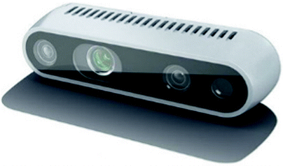
Intel Real Sense Depth Camera D435
-
Robot slider: moves the camera ring up and down
-
ChArUco board (7 × 5): Performs calibration of the camera coordinates (for aligning the three-dimensional XYZ camera coordinate system of the three cameras, and for aligning their Y axis (vertical axis) with the robot slider’s moving axis)
-
ArUco markers: To be installed at the location that we want to measure after performing calibration of the camera coordinates.

About the Intel Real Sense Depth Camera D435
The Intel Real Sense Depth Camera D435 is a stereo vision depth camera that can measure the distance to an object. The D435 includes an RGB camera and two depth sensors (infrared sensors). The specifications are listed in Table 1.
Robot Slider
The system which moves the ring with the three cameras mounted onto it up and down accurately is an RS1 single-axis robot from Misumi (Fig. 2). The specifications are listed in Table 2.

RS1 robot slider used in the experiment (manufactured by Misumi)
ArUco Markers
ArUco markers are used for estimating position and pose using a camera (Fig. 3). We use the ArUco markers included in OpenCV Contrib in OpenCV. ArUco markers are black and white squares in a binary format. Advantages of ArUco markers include that they are easy to detect and that they are fast to calculate.

ArUco marker
ChArUco Board
A ChArUco board is a combination of a chessboard and ArUco markers (Fig. 4). ArUco markers can be rapidly detected and have a diverse variety of patterns. However, one issue with ArUco markers is that the accuracy of the detection of the corner position is low. Therefore, the corner accuracy is compensated by combining the markers with a black and white chessboard. We used the ChArUco board sample in OpenCVContrib.

ChArUco board
3 Experiment Content
In this experiment, we mounted three D435 cameras to a ring-shaped fixture attached to the single-axis robot, as shown in Fig. 5. The cameras were mounted such that the entire ChArUco board was visible from all the cameras. Because the angles of the sensor cameras are fixed by the fixture, we adjusted the size of the ChArUco board and adjusted its height by pasting it onto a box.

Single-axis robot used in the experiment setup
First, we used the ChArUco board to calibrate the coordinate systems of the three cameras and the robot coordinate system. Next, we captured the ArUco markers in the cameras, and verified whether the three cameras could accurately measure their coordinates [18]. To verify this, we captured 9 ArUco markers simultaneously with the cameras as shown in Fig. 6 and verified whether the coordinates of the 9 markers were on a plane (Fig. 7). If the 9 measurement points are not on a plane, then we check the code in the program in Figs. 8 and 9 and change the settings for the ChArUco board and the ArUco markers to enable the accurate detection of coordinates. Once it can detect accurate coordinates, we move the single-axis robot up by 50 mm, 100 mm, and 150 mm, measure the coordinates of the ArUco markers, and evaluate the amount of error.

Measurement of 9 ArUco markers

9 ArUco markers on the 3D monitor

Source code for ChArUco board settings

Source code for ArUco markers.
The procedures for our experiment are described below. The camera calibration described above refers to finding the intrinsic parameters, which are unique to the camera, and the extrinsic parameters, which represent the pose of the camera in the world coordinate system. After completing camera calibration, it is possible to calculate the pixel within the camera image onto which an arbitrary point in the 3-dimensional XYZ coordinate system will be projected, and to calculate the position within the 3-dimensional coordinate system that corresponds to projection points in multiple cameras. It is also possible to compensate for distortion (tangential and radial directions) unique to each camera. In general, the calibration method that can be applied depends on the number of cameras and the available equipment. OpenCV implements the method proposed by [19].
3.1 Reading in the Calibration Image (ChArUco Board)
We attached three D435 cameras to the camera ring and captured the ChArUco board (7 × 5) in all the cameras. Although there is no rule that determines the number of static images that should be captured, capturing several tens of images will give sufficient calibration accuracy.
3.2 Processing the ChArUco Board Image
Here, we scan the corners of the ChArUco board from the lower left to the upper right corner and detect them. To increase the calibration accuracy, we edit the corners to sub-pixel accuracy (units of 0.5 pixels). Once all the corners have been detected correctly, the corners are drawn in 7 internally-defined colors. If not, all the corners are drawn in red. Therefore, we perform this process until all the corners are draw in the 7 internally-defined colors.
3.3 Formulation of Intrinsic and Extrinsic Parameters
First, we estimate the camera intrinsic parameters and the distortion coefficients. The intrinsic parameters correspond to A in the equation below.
-
m: Coordinates of the point projected onto the image plane
-
A: Camera intrinsic parameter matrix
-
R|t: Translation/rotation homogeneous coordinate matrix (extrinsic parameter matrix)
-
M: 3-dimensional coordinates in the world coordinate system
Next, we estimate the pose using the detected corners and the intrinsic parameters and obtain the rotation vector and the translation vector. Here, we convert the rotation vector to a matrix using Rodrigues’s rotation formula, combine the matrix with the translation vector, and obtain a 3 × 3 rotation matrix. Then, we include the translation vector to create a 4 × 3 matrix, and include (0,0,0,1) to obtain the 4 × 4 extrinsic parameter matrix (homogeneous coordinate transform matrix).
3.4 Estimation of Intrinsic Parameters and Extrinsic Parameters
Here, we estimate the camera’s extrinsic parameters ([R|t] in the above equation). The extrinsic parameters refer to the set of parameters that represent the transformation from the origin of the world coordinate system (3-dimensional coordinate system) to the camera coordinate system. In this calibration process, we estimate the camera’s intrinsic parameters and the extrinsic parameters for each view. First, we assume that the internal parameters are known, and estimate an initial value for the camera pose. We apply the global Levenberg-Marquardt optimization algorithm to minimize the re-projection error. The algorithm adjusts the extrinsic parameters such that the sum of the squares of the distances between the measurements of the actual points and the estimated points that were calculated using the intrinsic parameters and the camera pose is minimized. When the calibration is successful, the 3D monitor displays the location of the camera mounted at D in red, the location of the camera mounted at B in green, and the location of the camera mounted at F in blue, as shown in Fig. 10.

Camera position after calibration
3.5 ArUco Marker Measurement Evaluation Experiment
As shown in Fig. 11, we placed one ArUco marker on the ChArUco board (7 × 5) and measured its location. Then, we moved the robot slider by 50 mm three times and measured the location of the ArUco marker until the robot slider reached 150 mm.

Placing ArUco marker on top of the ChArUco board
4 Experiment Results
Here, we mounted the three cameras onto the ring, moved the robot slider up and down, and checked whether the amount of change in the measured location of the ArUco marker matched the amount of movement of the ring.
First, the locations at which cameras can be installed and the locations at which the cameras were installed are shown in Fig. 12. Figures 13, 14, and 15 are from a video that was captured in Visual Studio. In the 3-dimensional XYZ space that is shown (the Y axis is the vertical axis, and XZ is the horizontal plane), the red line represents the X axis, the blue line represents the Y axis, and the green line represents the Z axis. Figure 13 shows an image that was captured by Camera_0 mounted at location B (green circle), Fig. 14 shows an image that was captured by Camera_1 mounted at location D (red circle), and Fig. 15 shows an image that was captured by Camera_2 mounted at location F (blue circle). We also changed the locations of the cameras and took the measurements; however, because there is almost no error in the coordinates, the placement of the cameras did not have an impact. Next, Figs. 16, 17, and 18 represent the coordinates of one ArUco marker on the 3D monitor from three directions using the three cameras. The locations of Camera_0, Camera_1, and Camera_2 are each shown with a large green, red, and blue box. Meanwhile, the ArUco markers measured by the cameras are shown with a small green, red, and blue box. These figures show that the small green, red, and blue boxes perfectly overlap, which means that the cameras can measure the coordinates of the ArUco marker accurately without any interference between the cameras’ depth sensors (infrared sensors).

Positions at which cameras can be mounted.

Camera_0 video. (Color figure online)

Camera_1 video. (Color figure online)

Camera_2 video. (Color figure online)

Coordinate_1 of ArUco marker where 3 points overlap. (Color figure online)

Coordinate_2 of ArUco marker where 3 points overlap. (Color figure online)

Coordinate_3 of ArUco marker where 3 points overlap. (Color figure online)
In addition, Figs. 19, 20, and 21 show the 3D monitor images when the camera ring is moved in increments of 50 mm in the Y-axis direction by the robot slider. The images show that as the cameras move further away from the ArUco marker, error appears in the measured location. The error is represented in the graph shown in Fig. 22, which shows a plot of the change in the location of the ArUco marker.

Coordinates when the single-axis robot is moved in the Y-axis direction by 50 mm.

Coordinates when the single-axis robot is moved in the Y-axis direction by 100 mm.

Coordinates when the single-axis robot is moved in the Y-axis direction by 150 mm.

Coordinates when the single-axis robot is moved in the Y-axis direction by increments of 50 mm. (Color figure online)
Next, we explain the graph shown in Fig. 22. First, the coordinate of the vertical (Y) axis of Camera_0 (yellow line) was 0 mm, the coordinate of the vertical (Y) axis of Camera_1 (red line) was 0.6 mm, and the coordinate of the vertical (Y) axis of Camera_2 (blue line) was 4.4 mm. This shows that the error in the measurement of the ArUco marker location has a minimum of below 1 mm, and a maximum of 5 mm. This is the initial error. According to surgeons, the acceptable range for error is several mm for neurosurgery, and approximately 1 cm for liver surgery. Therefore, this amount of error will not have a large impact on surgery.
Next, when we moved the camera ring by 50 mm, the coordinate of the vertical (Y) axis of Camera_0 was 52.4 mm, the coordinate of the vertical (Y) axis of Camera_1 was 54.7 mm, and the coordinate of the vertical (Y) axis of Camera_2 was 52.5 mm. This shows that the error was approximately 4 mm at maximum. Next, when we moved the camera ring by 100 mm, the coordinate of the vertical (Y) axis of Camera_0 was 111.4 mm, the coordinate of the vertical (Y) axis of Camera_1 was 115.9 mm, and the coordinate of the vertical (Y) axis of Camera_2 was 110.0 mm.
This shows that an additional error of approximately 15 mm appeared. Lastly, when we moved the camera ring by 150 mm, the coordinate of the vertical (Y) axis of Camera_0 was 166.9 mm, the coordinate of the vertical (Y) axis of Camera_1 was 169.0 mm, and the coordinate of the vertical (Y) axis of Camera_2 was 162.6 mm. This shows that an error of approximately 20 mm appeared.
These results show that as the ArUco marker moves further away from the camera, the measurement error of the ArUco marker increases. If the cameras are raised too far, the error can exceed the limit for surgery.
In addition, the location of the ArUco marker varied severely when the red line was near 50 mm and 150 mm and when the blue line was near 100 mm. These variations are not due to physical vibrations of the robot slider or the camera ring but are rather due to pixel digital error that comes from fluctuations of the pixel in which the ArUco marker is captured.
Letters of the alphabet are assigned to locations A through F. The cameras can be mounted at these locations.
5 Conclusions and Future Works
In this study, we calibrated three D435 RGB/depth cameras by aligning three 3-dimensional camera coordinate systems and aligning their Z-axis with the moving axis of a robot slider. We moved the robot slider up by 50 mm twice and evaluated whether the change in the measured location of the marker measured by the three cameras matches the displacement. The results show that as the distance between the camera and the marker increased, the error in the location of the marker also increased. However, the direction of the error was not random, and was constant. The error might be due to the impact of the offset in the installation of the camera ring or the robot slider. Therefore, we will use separate devices, such as a leveler, to evaluate whether this factor has an impact. Furthermore, the location also sometimes varies due to the digital error in the image pixels. It is possible to modify the software so that the 3-dimensional location of the marker becomes constant by processing the position in the image in which the marker was visible to sub-pixel level less than 0.5, or by using a moving average to measure the position. Lastly, because the angle at which the cameras capture the surgical area is currently constant, the surgical area can sometimes leave the camera’s field-of-view as the robot slider moves up. Therefore, we want to use a fixture that allows the angle to be adjusted freely so that the camera will always capture the surgical area even when the camera ring is moved up and down by the robot slider.
References
Matsumoto, N., et al.: A minimally invasive registration method using surface template-assisted marker positioning (STAMP) for image-guided otologic surgery. Otolaryngol.—Head Neck Surg. 140(1), 96–102 (2009)
Hong, J., Hashizume, M.: An effective point-based registration tool for surgical navigation. Surg. Endosc. 24(4), 944–948 (2010)
Ieiri, S., et al.: Augmented reality navigation system for laparoscopic splenectomy in children based on preoperative CT image using optical tracking device. Pediatr. Surg. Int. 28(4), 341–346 (2012)
Mahmud, N., Cohen, J., Tsourides, K., Berzin, T.M.: Computer vision and augmented reality in gastrointestinal endoscopy. Gastroenterol. Rep. (Oxf) 3(3), 179–184 (2015). https://doi.org/10.1093/gastro/gov027
Pessaux, P., Diana, M., Soler, L., Piardi, T., Mutter, D., Marescaux, J.: Towards cybernetic surgery: robotic and augmented reality-assisted liver segmentectomy. Langenbecks Arch. Surg. 400(3), 381–385 (2015)
Watanabe, K., et al.: Brain shift simulation controlled by directly captured surface points. In: Proceedings of 38th Annual International Conference of the IEEE Engineering in Medicine and Biology Society, Sessions: Ignite_Theme 2_Fr2, Poster Session III, Orlando, FL, USA (2016)
Yano, D., Koeda, M., Onishi, K., Noborio, H.: Development of a surgical knife attachment with proximity indicators. In: Marcus, A., Wang, W. (eds.) DUXU 2017. LNCS, vol. 10289, pp. 608–618. Springer, Cham (2017). https://doi.org/10.1007/978-3-319-58637-3_48
Watanabe, K., Yoshida, S., Yano, D., Koeda, M., Noborio, H.: A new organ-following algorithm based on depth-depth matching and simulated annealing, and its experimental evaluation. In: Marcus, A., Wang, W. (eds.) DUXU 2017. LNCS, vol. 10289, pp. 594–607. Springer, Cham (2017). https://doi.org/10.1007/978-3-319-58637-3_47
Sengiku, A., et al.: Augmented reality navigation system for robot-assisted laparoscopic partial nephrectomy. In: Marcus, A., Wang, W. (eds.) DUXU 2017. LNCS, vol. 10289, pp. 575–584. Springer, Cham (2017). https://doi.org/10.1007/978-3-319-58637-3_45
Onishi, K., Miki, Y., Okuda, K., Koeda, M., Noborio, H.: A study of guidance method for AR laparoscopic surgery navigation system. In: Marcus, A., Wang, W. (eds.) DUXU 2017. LNCS, vol. 10289, pp. 556–564. Springer, Cham (2017). https://doi.org/10.1007/978-3-319-58637-3_43
Noborio, H., et al.: Fast surgical algorithm for cutting with liver standard triangulation language format using Z-buffers in graphics processing unit. In: Fujie, M.G. (ed.) Computer Aided Surgery, pp. 127–140. Springer, Tokyo (2016). https://doi.org/10.1007/978-4-431-55810-1_11
Noborio, H., Aoki, K., Kunii, T., Mizushino, K.: A Potential function-based scalpel navigation method that avoids blood vessel groups during excision of cancerous tissue. In: Proceedings of the 38th Annual International Conference of the IEEE Engineering in Medicine and Biology Society (EMBC 2016), pp. 6106–6112 (2016)
Noborio, H., Kunii, T., Mizushino, K.: Comparison of GPU-based and CPU-based algorithms for determining the minimum distance between a cusa scalper and blood vessels. In: BIOSTEC 2016, The SCITEPRESS Digital Library, pp. 128–136 (2016)
Watanabe, K., et al.: A mechanical system directly attaching beside a surgical bed for measuring surgical area precisely by depth camera. In: Proceedings of the 10th MedViz Conference and the 6th Eurographics Workshop on Visual Computing for Biology and Medicine (EG VCBM), pp. 105–108 (2016)
Watanabe, K., et al.: Capturing a brain shift directly by the depth camera kinect v2. In: Proceedings of 38th Annual International Conference of the IEEE Engineering in Medicine and Biology Society, Sessions: Ignite_Theme 4_Fr1, Poster Session II, Orlando, FL, USA (2016)
Nonaka, M., Watanabe, K., Noborio, H., Kayaki, M., Mizushino, K.: Capturing a surgical area using multiple depth cameras mounted on a robotic mechanical system. In: Marcus, A., Wang, W. (eds.) DUXU 2017. LNCS, vol. 10289, pp. 540–555. Springer, Cham (2017). https://doi.org/10.1007/978-3-319-58637-3_42
Nonaka, M., Chikayama, Y., Kayaki, M., Koeda, M., Tachibana, K., Noborio, H.: A useful robotic-mechanical system for measuring a surgical area without obstructing surgical operations by some surgeon. In: Kurosu, M. (ed.) HCI 2018. LNCS, vol. 10902, pp. 43–52. Springer, Cham (2018). https://doi.org/10.1007/978-3-319-91244-8_4
OpenCV 3.4.4 Homepage. https://docs.opencv.org/3.4.4/index.html. Accessed 31 Jan 2019
Zhang, Z.: A flexible new technique for camera calibration. IEEE Trans. Pattern Anal. Mach. Intell. 22(11), 1330–1334 (2000)
Acknowledgment
This research has been partially supported by the Collaborative Research Fund for Graduate Schools (A) of the Osaka Electro-Communication University, and a Grant-in-Aid for Scientific Research of the Ministry of Education, Culture, Sports, Science and Technology (Research Project Number: JP26289069 and 17K00420).
Author information
Authors and Affiliations
Corresponding author
Editor information
Editors and Affiliations
Rights and permissions
Copyright information
© 2019 Springer Nature Switzerland AG
About this paper

Cite this paper
Nonaka, M., Noborio, H., Onishi, K., Tachibana, K., Watanabe, K., Mizushino, K. (2019). Multi-camera Coordinate Calibration and Accuracy Evaluation for Robot Control. In: Kurosu, M. (eds) Human-Computer Interaction. Recognition and Interaction Technologies. HCII 2019. Lecture Notes in Computer Science(), vol 11567. Springer, Cham. https://doi.org/10.1007/978-3-030-22643-5_40
Download citation
DOI: https://doi.org/10.1007/978-3-030-22643-5_40
Published:
Publisher Name: Springer, Cham
Print ISBN: 978-3-030-22642-8
Online ISBN: 978-3-030-22643-5
eBook Packages: Computer ScienceComputer Science (R0)