
Abstract
Endpoint fusing is a highly crucial part in the process of sketch beautification, in which sketch is tackled into tidier one with a certain rule. This paper proposes a new method of endpoint fusing based on angular histogram for axonometric drawing of online freehand sketched polyhedrons, which is an improvement over the existing fusing approaches and lays a solid foundation for further 3D reconstruction. The approach consists of four main steps: Firstly, grouping and paralleling gestures that are the results of recognizing and fitting inputting strokes, and producing correction drawing according to the angular histogram of gestures. Then, clustering endpoints by using adaptive tolerance zone, which refers to grouping adjacent endpoints when both fall within each other’s tolerance circles. After that, determining “coordinate system-weight criteria” and getting the order of endpoints fusing. Finally, connecting session is performed under the premise of keeping parallel producing for a neat drawing with perfect connections at the strokes intersection. The method here has been tested with a sketch regularization prototype system called FSR_EF, and experimental results on various freehand axonometric sketches show that it provides a good solution to improve these limitations occurring in most existing sketching systems which only simply conduct pinching without considering context of the sketches. And the test results largely reserve the user’s initial intentions and proves that the method achieves an acceptable outcome.
You have full access to this open access chapter, Download conference paper PDF
Keywords
- Endpoint fusing
- Online freehand sketching
- Polyhedrons
- Axonometric projection
- Parallel processing
- Sketch regularization
1 Introduction
As the early phase of the design process, conceptual design aimed at obtaining the basic form of product and rapidly express their creative thought with a visual and vivid way for further detailed design [1]. An excellent designer requires good creativities and the capability to present them fluently in a certain way. Freehand sketch is such a representation that can convert and perceive designers’ ideas. It also is the most natural and direct means of expressing design innovation and capturing memory. In addition, it’s also help to show designers’ design thinking and creative activity. Freehand sketch draws fast and produces graceful and natural lines, which impresses people with a strong artistic appeal. Our surveys continued to show that traditional mechanical designer had been accustomed to carry on conceptual design with paper and pencil not computers. Almost 100% drawings from conceptual design are preserved in the form of freehand sketch. However, drawings are always confusing and difficult to correct after several modifications in the process of freehand sketching. Moreover, it’s impossible to save the whole design process, and all retained drawings cannot compose a comprehensive design due to the lacking of effectively interactive characteristic. With the rapidly developing of computer technology, online sketches recognition overcomes the shortages of traditional design method and people could interact effectively with work. Such patterned drawing software tools as Visio, Microsoft Office in addition to many CAD systems, finish sketches with overly relying on precise digital information and frequent menu items [2], hence their interface is so typically cumbersome to use and hamper design’s creative flow [3] that it’s not sufficiently suitable for the fuzzy freehand conceptual design.
In order to well support the freehand sketching design, an efficient and robust sketch interface [4] is necessary, where users can draw sketches on a tablet with a digital pen. The sketch interface is designed to bridge the gap between freehand sketches and computer-based modeling programs, combining some of the features of pencil-and-paper sketching and some of the characteristic of CAD systems to provide a natural, convenient interface to approximate sketch modeling [5]. As early as 1963, Sutherland [6] presented the first interactive sketch system, Sketchpad, which inputted graphs over the screen surface with a light pen. It didn’t achieved a desired result due to limitations in performance of the machine and capability of the recognition, but provided a very promising technology. SKETCH [5] allowed users to draw simple geometric figures using a set of predefined gestures. Meyer [7] described a tool called EtchaPad for sketching widgets in the Pad++ system, including many layout operations. Igarashi [8] explained an original sketch into a diagram that looks like a carefully drafted drawing. Zou [9] showed such system that allows users to make an initial sketch by drawing strokes using a pen, reconstruct it, and subsequently add new strokes. After inputting the freehand sketch, computer needs to collect, analyze feature information of sketch, and quickly conduct recognition, interpretation for producing the 2D line drawing of 3D object.
As a symbol of directly recording human consciousness, freehand sketch possesses a variety of features, such as diverse styles, abstraction, imprecision, etc. It’s particularly difficult for computer to perfectly interpret the user’s design intention by the sketch [4]. Although there has been so many sketch systems described above, producing more sophisticated systems that can improve the shortcomings before for further 3D reconstruction of polyhedral models are necessary. As a very prospective technology without complicated commands, computer sketch interface has been highly focused over recent years. A lot of works has been gone on to research sketch regularization in sketching systems, but there are still great difficulties in systems and even restriction on it’s development. In addition, it’s a burdensome task presently to design a perfect sketching systems overcoming these inevitable factors. Sketching interpretation is closely related to specific application fields, such as electrical diagrams [10], structure charts of chemical molecules, cartoon animation [11] or architectural drawing [12] etc.
This paper primarily is concerned about the regularization of axonometric drawing of online freehand sketched polyhedrons. Usually a comprehensive projection of 3D object result always requires perfect connection at the strokes intersection, but it is difficult for the user to complete a completely closed sketch, the sketchy line is always not closed or forms a cross near its endpoints. As a consequence, the process of connecting endpoint of strokes correctly, namely endpoint fusing, is a very crucial link during the process of sketch regularization. In the mean time, most of the current systems of freehand sketch complete this module without considering context of sketches, which makes system more liable to make mistakes in interpreting the user’s original intentions. Therefore, It remains a issue deserving of further study in online sketch regularization, and specifically addressing the open challenge in this paper.
This paper does an exploratory study about axonometric drawing of online freehand sketched polyhedrons, specifically, endpoints fusing in the process of sketch regularization. Axonometric drawing of freehand sketched polyhedrons consists of a set of line segments whose parallelism is inconsistent and junctions are not neat. And these improper endpoints are great barriers for both correct shape recognition and well regularization. There are considerable researches dedicating to endpoint fusing of freehand sketch, and most of existing approaches are based on tolerance zones of strokes each other. Pavlidis and van Wyk [13] proposed a clustering scheme based on statistical analysis to chose a tolerance zone. Durgun [14] took a percentage of the associated line length as the result of threshold value. And Sun [15] put forward that endpoint of edges should be adjacent to each other if the length of the extension is less than a certain threshold after the shorter strokes extending to intersect with another. Obviously, the methods above cannot be used to obtain the most reliable results. A simple method of connecting endpoints that are purely closer than a minimal threshold distance is far from sufficient. And adopting a relatively fixed threshold value to judge the clustering between strokes, too large one may neglects fine details and lead to fusing overly, too small one may leave endpoints that are supposed to be connected unlinked. The size of the tolerance zone should be determined by the sensibility to the detail in the close vicinity of the endpoint. Lipson [16] proposed a method based on the average distance from each original endpoint to entities in the sketch, which includes the distance from a endpoint to its own entity, namely, half the entity. The smallest average distance is regarded as the size of tolerance circle. The next step involves grouping endpoints falling within each other’s tolerance circles, and the procedure is repeated as more and more endpoints are clustered. Finally, each cluster is replaced by one vertex that is the center of each group endpoints. Wang [17] brought up a novel endpoint fusing approach builded on adaptive tolerance zone to improve Lipson’s and make the threshold zone more adaptable. However, both of them simply fused endpoints and viewed each entity in isolation without considering the relationship of relative position between all strokes in the final stage of the endpoint integration. It to a certain extent undermines the interrelation between various entities and mistakes user’s initial rendering intention. Ku [18] presented a method mainly focusing on the interpretation of online multi-stroke, which translates into five processing phases: stroke classification, strokes grouping and fitting, endpoint clustering, parallelism correction, and in-context interpretation. The shortcomings of this approach include some aspects as follows. First, the method largely lost the initial position information of strokes on account of proceeding parallelism correction after endpoint clustering. Second, the method directly conduct endpoint fusing of gestures with errors and may lead to irregular distortion of projection drawings. Thirdly, the implement algorithm of this method is relatively complicated. Overall, the different fusion methods above on various studies have a certain rationality. Meanwhile, obtaining an excessive fixed tolerance value by experimental statistical analysis or a percentage of the associated line length will lead to an unreliable result. And the method based on adaptive tolerance zone [19] finally cracks the problem, but still exists some deficiencies in fusion manner.
In this paper, we propose a novel endpoint fusing method for axonometric drawing of online freehand sketched polyhedrons, based on our previous research [17], to effectively tidy-up sketches. Firstly, parallelism correction is used to dispose gestures, the result of recognizing and fitting inputting strokes, according to the angular histogram of strokes. Secondly, clustering endpoints using adaptive tolerance zone and obtaining the order of endpoints fusing with “coordinate system-weight criteria”. At last, endpoints fusing is carried out in order under the premise of a certain error. This approach adopted a more reasonable method to beautify axonometric drawings of online freehand sketched polyhedrons. In addition, it overcomes the limitation of simple joining gestures without considering in-context information of sketches, and avoids larger shape error of drawings. In addition, a sketching interactive system named FSR-EF that can address the limitations discussed above is proposed. The work perfects the previous methods as well as form the foundation upon further 3D reconstruction of polyhedral models.
2 New Methods
2.1 Overview of Connecting Endpoints
We are going to exploit a system that intends to beautify the freehand axonometric drawing of freehand sketched polyhedron and converts the drawing into a neat line drawing, especially, in terms of endpoints fusing. First of all, as the input of the algorithms in this paper, gestures from recognizing and fitting strokes can be represented by a sequence of line segments \( \{ L_{i} ; \, 0 \le i < N\} \), and each angle \( \{ \theta_{i} ; \, 0 \le i < N,\;\;0 \le \theta_{i} < 180\} \) is the included angle between x-axis and every line segment, where \( N \) is the number of gestures in gesture drawing. The approach here consists of four main steps that are as follows: (1) paralleling gestures under angular histogram and the angle-thresh \( \Delta \delta \), with producing a correction drawing; (2) clustering endpoints by using adaptive tolerance zone; (3) sorting order for the “coordinate systems” \( \{ C_{i} ; \, 0 \le i < H\} \) in accordance with weighting rule; (4) specific part of endpoints fusing is carried out in order. The concrete flowchart of the method in this paper is shown in Fig. 1.

Process of endpoints fusing for axonometric drawing of online freehand sketched polyhedrons
2.2 Fusion Algorithm
The endpoints usually don’t strictly intersect at nodes with existing lots of messy junction, hence we need to connect them tidily. In addition, this section aims to complete concrete operations of endpoint fusing algorithm.
Parallelism processing.
Before endpoints joining, we would perform the parallelism processing to calibrate the linearity of gestures in a freehand axonometric drawing with hoping for further improving the reasonableness and accuracy for sketch regularization. we need to extract the in-context information of gesture, then infer structural meaning of sketch from which and adjust messy gestures by imposing linearity constraints and end up with a correction drawing. Generally, we hypothesize that gestures whose angle difference is within angle-thresh \( \Delta \delta \) are supposed to be regarded as parallelism in this paper, specially gestures with angles close to the directions along axis in axonometric projection.
Figure 2 shows the major contents for parallelism correction, and the process is summarized by the following steps:

Parallelism correction (a) gesture drawing. (b) correction drawing. (c) comparison of (a) and (b).
-
Step1: Extract the endpoints and angle of each gesture \( \{ L_{i} ;\;0 \le i < 18\} \), where \( L_{i} \) represents the gestures whose sequence number is i, and \( \theta_{i} (0 \le \theta_{i} \le 180) \) symbolizes the angle value of \( L_{i} \).
-
Step2: Make angular histogram according to the values of i and angle value \( \theta_{i} \). An example shown in Fig. 3.
Fig. 3. 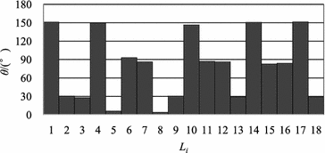
Angular histogram of gesture drawing in Fig. 2
-
Step3: Divide gestures in Fig. 3 into groups \( Q_{s} \) by angle-thresh \( \Delta \delta \): \( Q_{1} = \left\{ {L_{i} ;\;i = 1,\;4,\;10,\;14,\;17} \right\} \); \( Q_{2} = \left\{ {L_{i} ;\;i = 2,\;3,\;9,\;13,\;18} \right\} \); \( Q_{3} = \left\{ {L_{i} ;\;i = 5,\;8} \right\} \); \( Q_{4} = \left\{ {L_{i} ;\;i = 6,\;7,\;11,\;12,\;15,\;16} \right\} \).
-
Step4: Take average angle value \( \{ \bar{\theta }_{s} ;\;s = 1,\;2,\;3,\;4\} \) for each set of gestures, and respectively correct them by it.

The procedure ends up with a correction drawing, as shown in Fig. 2(b). Figure 2(c) describes the comparison between two drawings before and after treatment, where the dark one expresses gesture drawing, the light one is correction drawing.
Clustering Endpoints.
There are a lot of unconnected endpoints in correction drawing, it’s necessary to categorize, store them in one correction drawing and conducive to reasonable connecting. In this paper, we call the potential connection points quasi-fusing endpoints and adopt the method of tolerance zone with variable coefficients to achieve endpoints clustering. The size of tolerance circle here will vary with the whole-text information of sketch. Quasi-fusing endpoints could be grouped into a cluster if they fall within each other’s tolerance circle, next repeating the procedure until more and more endpoints are grouped. Each cluster will finally be replaced by one vertex that is explained in more detail below. Moreover, if the number of quasi-fusing endpoints in one cluster greater than 3 or less than 2, it also can be adjusted by appropriately broaden or narrow the tolerance circle. Figure 4 shows the endpoints clustering results.

Determination of clustering endpoints
Sort Order for the “coordinate system”.
Polyhedron, the planar body with trihedral vertices, is the primary studying object in this paper. And the algorithm here can be easily generalized to curved surface objects. For projection drawing of freehand sketched polyhedrons, we assume that there exists one coordinate system at each node including three quasi-fusing endpoints respectively in three different line segments. And directions of the three line segments also individually represent the 3 directions of the coordinate system, each coordinate system consists of a few quasi-fusing endpoints.
Above all, coordinate systems are classified into several groups by determining whether they are consistent in the orientations, and the groups of coordinate systems whose weight is biggest are called level 1 coordinate system \( G_{1} \), by that analogy, the second most are called level 2 coordinate system \( G_{2} \), the third most are called level 3 coordinate system \( G_{3} \), and so on. Because of the level 1 coordinate system \( G_{1} \) makes up the biggest overweight, it’s most rational to first tackle the quasi-fusing endpoints in \( G_{1} \) and others in turn, we call the rule “coordinate system-weight criteria”. There are 12 nodes \( \{ d_{i} ;\;0 \le i < 12\} \) in the correction drawing as shown in Fig. 5, correspondingly existing 12 coordinate systems \( \{ C_{i} ;\;0 \le i < 12\} \) here. According to “coordinate system-weight criteria”, the coordinate systems can be divided into 3 groups: \( G_{1} \; = \{ C_{i} ;\;i = 1,2,3,8,9,10,11,12\} \), \( G_{2} \; = \left\{ {\left\{ {C_{i} ;\;i = 4,6} \right\},\left\{ {C_{i} ;\;i = 5,7} \right\}} \right\} \). It a priority to tidy-up and connect quasi-fusing endpoints in \( G_{1} \), and quasi-fusing endpoints in \( G_{2} \), \( G_{3} \) one by one.

Correction drawing
Connecting Endpoint.
In freehand sketched projection drawing, there are three cases after clustering quasi-fusing endpoints: one points clustering, two points clustering and three points clustering \( (K = 2,\;3) \). To keep consistent with description above, line segments in correction drawing can be expressed as \( \{ l_{i} ;\;0 \le i < N\} \), endpoints of each line segment is \( \{ d_{ij} ;\;0 \le i < N,j = 0,1\} \), and the tolerance of each quasi-fusing endpoints is \( \{ R_{ij} ;\;0 \le i < N,j = 0,1\} \). The sequence of line segments consisting of cluster points in one group is \( \{ l_{u} ,\;l_{v} ,\;l_{w} ;\;0 \le u,\;v,\;w < N\} \), the coordinate systems is \( \{ C_{z} ;\;0 \le z < H\} \), and the numbers of line segments that have been involved in the process of endpoints fusing is M \( (M = 0,1,2,3) \), where H is the total number of nodes in correction drawing.
Example is shown in Fig. 6, specific steps of algorithm in this paper are as follows:

An example for endpoints fusing
-
Step1: Cluster quasi-fusing endpoints \( \{ d_{ij} ;\;0 \le i < N,j = 0,1\} \) in correction drawing into H group by tolerance circle of each endpoint \( R_{ij} \), subsequently with H (\( H = 12 \)) nodes and H coordinate systems \( \{ C_{z} ;\;0 \le z < H\} \). (see Fig. 7);
Fig. 7. 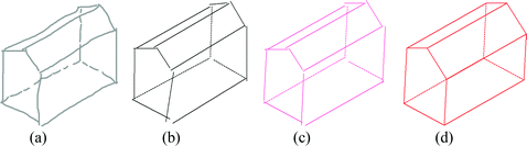
(a) sketch. (b) gesture drawing. (c) correction drawing. (d) final result.
-
Step2: Group coordinate systems \( \{ C_{z} ;\;0 \le z < H\} \), and sequentially obtain several set of coordinate systems \( G_{1} \), \( G_{2} \), \( G_{3} \): \( G_{1} = \left\{ {C_{1} \left\{ {l_{1} ,l_{2} ,l_{16} } \right\},} \right.C_{2} \left\{ {l_{1} ,l_{3} ,l_{12} } \right\}, \) \( C_{3} \left\{ {l_{2} ,l_{4} ,l_{11} } \right\},C_{8} \left\{ {l_{9} ,l_{10} ,l_{15} } \right\}, \) \( C_{9} \left\{ {l_{11} ,l_{14} ,l_{18} } \right\},C_{10} \left\{ {l_{12} ,l_{13} ,l_{17} } \right\}, \) \( C_{11} \left\{ {l_{13} ,l_{14} ,l_{15} } \right\}\left. {,C_{12} \left\{ {l_{16} ,l_{17} ,l_{18} } \right\}} \right\} \); \( G_{2} = \left\{ {C_{4} \left\{ {l_{3} ,l_{5} ,l_{6} } \right\}} \right.,C_{6} \left\{ {l_{6} ,l_{8} ,l_{9} } \right\}, \) \( \left.C_{5} \left\{ {l_{4} ,l_{5} ,l_{7} } \right\},C_{7} \left\{ {l_{7} ,l_{8} ,l_{10} } \right\}\right\} \);
-
Step3: Determine the value of \( M \) in each \( C_{z} \), and respectively collate the sequence of line segments \( \{ l_{u} ,\;l_{v} ,\;l_{w} ;\;0 \le u,\;v,\;w < N\} \) in the same coordinate system \( C_{z} \). Store \( l_{u} \) preferentially if it has already been connected;
-
Step4: When \( M = 3 \), \( K = 3 \), \( l_{u} \) and \( l_{v} \) intersect at P by extending the two line segments. Keep the endpoint that has been addressed in \( l_{w} \) still, and another endpoint in \( l_{w} \) is made into point \( P \). In this case, because all the line segments in one coordinate system has participated in endpoints joining, it’s inevitable that there will be fusion errors. For example, we implement connection in \( C_{11} \{ l_{13} ,l_{14} ,l_{15} \} \). Because \( l_{13} \), \( l_{14} \) and \( l_{15} \) have been already tackled, first node 11 is created by intersection of \( l_{13} \) and \( l_{14} \), then make \( l_{15} \) coincident with node 11, and cause \( l_{15} \) rotating in the meantime with certain errors;
-
Step5: When \( M = 0,1,2 \), \( K = 2 \), \( l_{u} \) and \( l_{v} \) intersect at \( P \) by extending the two line segments;
-
Step6: When \( M = 0,1,2 \), \( K = 3 \), first \( l_{u} \) and \( l_{v} \) intersect at \( P \) by extending the two line segments. Then translate \( l_{w} \) until one endpoint of it is equal to \( P \) and keep it’s angle constant. Using \( C_{6} \{ l_{6} ,\;l_{8} ,\;l_{9} \} \) as an example, first node 6 is created by intersection of \( l_{6} \) and \( l_{9} \). Then translate \( l_{8} \) and make it’s one endpoint equal to node 6, with the angle constant of \( l_{8} \).

The process of endpoints fusing in this paper can be classified into two stages: the phase of error-free regularization and the part with errors. At the beginning of endpoints fusing, almost all of line segments in the first few coordinate systems are in unprocessed state. There are only three forms of translation, extension and intersection in this stage with \( M = 0,\;1,\;2 \). Therefore, the stage goes on with zero error. For the latter, all of line segments have involved the endpoints joining and would be carried out the operation of rotating, resulting in the change of angles and accumulation of errors to last level coordinate systems. The most important factors in the process of sketch regularization is to collect drawing intentions of users. however, it is difficult for the user to draw a perfectly sketch, the sketchy line is usually not neat, not absolutely straight, and not entirely parallel between two ones, etc. The method in this paper solves the problems that occurred in user’s drawing. We propose a criteria, the angle difference between before and after fusion, is regarded as the assessment for the excellent performance of the method to endpoints fusing.
3 Implementation
Online freehand sketch recognition system FSR is independently researched and developed on Windows 7 using Visual C++ by the team which the author belongs to. The input device is a mouse, and it will interpret the freehand sketch into a neat and clear 2D line drawing. we asked artists to manually draw projection drawing of online freehand sketched polyhedrons, the regularization process and results are summarized in Fig. 7. In addition, the test results largely ensure the output sketch meaningful and show that the approach can support conceptual design based on axonometric drawing of online freehand sketched polyhedrons while achieving a satisfactory interpretation.
4 Conclusion
This paper have described a novel method for endpoint fusing of online freehand polyhedrons projection in the prototype FSR_EF system. It improves the existing endpoint fusing methods for online freehand sketched projection. And the test results turns out the better result from the method in this paper by being compared with existing other methods. The study here can improve the accuracy of the sketch regularization and possesses some reference value for the new generation of human computer interaction system supporting conceptual design. Meanwhile, the method here has some limitations. During regularizing some more complicated freehand sketched polyhedrons, there always are larger errors due to the lack of consideration of line-plane relation. The work presented here is only the part of our final sketched based 3D modeling system, and only studies online freehand sketched polyhedrons consisting of single stroke lines, not involving freehand sketched projection including multi-strokes and curves. And further research about how to process the problems above needs to be improved.
References
Song, B.H.: Research on computer supported intelligent sketching technology for product conceptual design. Northwestern Polytechnical University, D Xi’an (2003). doi:10.7666/d.y568835. (in Chinese) (宋保华. 面向产品概念设计的智能草图研究.D 西安: 西北工业大学)
Liu, W.: On-line graphics recognition: state-of-the-art. In: Lladós, J., Kwon, Y.-B. (eds.) GREC 2003. LNCS, vol. 3088, pp. 291–304. Springer, Heidelberg (2004). doi:10.1007/978-3-540-25977-0_27
Masry, M., Kang, D., Lipson, H.: A freehand sketching interface for progressive construction of 3D objects. J. Comput. Graph. 29, 563–575 (2005). doi:10.1145/1281500.1281541
Li, B., Lu, Y., Godil, A., et al.: A comparison of methods for sketch-based 3D shape retrieval. J. Comput. Vis. Image Underst. 119, 57–80 (2014). doi:10.1016/j.cviu.2013.11.008
Zeleznik, R.C., Herndon, K.P., Hughes, J.F.: SKETCH: an interface for sketching 3D scenes. In: Conference on Computer Graphics & Interactive Techniques, pp. 163–170 (2007). doi:10.1145/237170.237238
Sutherland, I.E.: Sketchpad: a man-machine graphical communication system (1963)
Meyer, J.: EtchaPad—disposable sketch based interfaces. In: Conference Companion on Human Factors in Computing Systems, pp. 195–196 (1996). doi:10.1145/257089.257258
Igarashi, T., Matsuoka, S., Kawachiya, S., et al.: Interactive beautification: a technique for rapid geometric design. In: 10th annual ACM symposium on User Interface Software and Technology, pp. 105–114 (1997). doi:10.1145/1281500.1281529
Zou, H., Lee, Y.: Constraint-based beautification and dimensioning of 3D polyhedral models reconstructed from 2D sketches. J. Comput. Aided Des. 39, 1025–1036 (2007). doi:10.1016/j.cad.2007.08.002
Jun-Wen, X.U., Liao, D.X., Wang, S.X., et al.: Recognition of on-line sketched electrical diagrams. J. Sci. Technol. Eng. 6, 034 (2007)
Zhang, S.H., Chen, T., Zhang, Y.F., et al.: Vectorizing cartoon animations. IEEE Trans. J. Visual. Comput. Graph. 15, 618–629 (2009). doi:10.1109/TVCG.2009.9
Ching, F.D.: Architecture: Form, Space, and Order. Wiley, New York (2014)
Pavlidis, T., Van Wyk, C.J.: An automatic beautifier for drawings and illustrations. In: ACM SIGGRAPH Computer Graphics, pp. 225–234 (1985). doi:10.1145/325165.325240
Durgun, F.B., Zgüç, B.: Architectural sketch recognition. J. Architectural Sci. Rev. 33, 3–16 (1990)
Sun, J.Y., Jin, X.Y., Peng, B.B., et al.: A method of fast on-line graphics recognition and regularization. J. Comput. Sci. 30, 172–176 (2003). (in Chinese) (孙建勇, 金翔宇, 彭彬彬, 等(2003) 一种快速在线图形识别与规整化方法. J 计算机科学. 30: 172-176)
Shpitalni, M., Lipson, H.: Classification of sketch strokes and corner detection using conic sections and adaptive clustering. J. Mech. Des. 119, 131–135 (1997). doi:10.1115/1.2828775
Wang, S.X., Yu, S.H.: Endpoint fusing of freehand 3D object sketch with Hidden-part-draw. In: 10th International Conference on Computer-Aided Industrial Design & Conceptual Design. IEEE Press, pp. 586–590 (2009). doi:10.1109/CAIDCD.2009.5375407
Ku, D.C., Qin, S.-F., Wright, D.K.: Interpretation of overtracing freehand sketching for geometric shapes. In: 14-th International Conference in Central Europe on Computer Graphics, Visualization and Computer Vision, pp. 263–270 (2006)
Wang, S.X., Gao, M.T., Qi, L.H.: Endpoint fusing of hand-drawing 3D projection sketches. J. Comput. Aided Des. Comput. Graph. 21, 81–87 (2009). (in Chinese) (王淑侠, 高满屯, 齐乐华 (2009). 在线手绘投影线图的端点融合. J 计算机辅助设计与图形学学报. 21: 81-87.)
Acknowledgements
This work is partly supported by National Natural Science Foundation of China (Grant No. 51105310), Natural Science Basic Research Plan in Shaanxi Province of China (Grant No. 2016JM6054),the Programme of Introducing Talents of Discipline to Universities (111 Project)of China (Grant No. B13044), the Open Project Program of the State Key Lab of CAD&CG (Grant No. A1615) of Zhejiang University.
Author information
Authors and Affiliations
Corresponding author
Editor information
Editors and Affiliations
Rights and permissions
Copyright information
© 2017 Springer International Publishing AG
About this paper
Cite this paper
Wang, S., Zhang, Q., Wang, S., Gao, M., Jing, X., Hui, X. (2017). Endpoint Fusing Method for Axonometric Drawing of Online Freehand Sketched Polyhedrons. In: Kurosu, M. (eds) Human-Computer Interaction. User Interface Design, Development and Multimodality. HCI 2017. Lecture Notes in Computer Science(), vol 10271. Springer, Cham. https://doi.org/10.1007/978-3-319-58071-5_40
Download citation
DOI: https://doi.org/10.1007/978-3-319-58071-5_40
Published:
Publisher Name: Springer, Cham
Print ISBN: 978-3-319-58070-8
Online ISBN: 978-3-319-58071-5
eBook Packages: Computer ScienceComputer Science (R0)