
Abstract
We have developed a surgical navigation system for robot-assisted laparoscopic partial nephrectomy (RALPN). In this system, a three-dimensional computer graphics (3DCG) model generated from each patient’s computed tomography image is overlaid on the endoscopic image, and we control it manually to navigate the vascular structure and tumor location in real time. The position and orientation of the 3DCG model is calculated from the optical flow of the endoscopic camera images, which enables the model to move semi-automatically. We conducted 20 navigations for RALPN from April 2014 to December 2016. Our support system worked appropriately and was helpful to localize the tumor and determine the resection line.
You have full access to this open access chapter, Download conference paper PDF
Keywords
1 Introduction
In recent years, progress in diagnostic radiographic imaging technology and a heightened awareness of early detection of cancer have facilitated incidental discovery of small renal tumors. Therefore, while radical nephrectomy, which was conventionally the gold standard treatment for localized renal cell carcinoma, is decreasing as the treatment of choice, partial nephrectomy has become the standard therapy for small renal cell carcinoma. In addition, laparoscopic surgery has become more widespread because of the progression in surgical techniques and medical engineering as well as the requirement for minimally invasive surgery [1]. Robot-assisted laparoscopic partial nephrectomy (RALPN) is an excellent minimally invasive treatment that can achieve both cancer control and renal function preservation. RALPN has been conducted in several hospitals to realize higher-precision surgery.
A limitation of RALPN is the impairment of haptic feedback. This problem has not yet been resolved; therefore, surgeons should discern the border between the tumor and normal kidney only from visual information. Conventionally, we have used ultrasonography during partial nephrectomy to identify the location and margin of tumors. However, ultrasonography is not always sufficient for discerning the precise border when the tumor is totally endophytic or appears relatively isoechoic. Thus, proper image guidance can offer a potential clinical advantage with respect to accurate anatomic identification and unambiguous dissection of a tumor, contributing to a safe and rapid surgical operation [2, 3]. Additionally, the number of RALPNs are sharply increasing because RALPN became covered by the national health insurance system of Japan in April 2016. We herein describe our development of a surgery support system for RALPN in April 2014.
2 Overview of Navigation System
We developed a RALPN navigation system with augmented reality technology using the following three steps. First, we generated a three-dimensional computer graphics (3DCG) model that includes a kidney, arteries, veins, tumors, and urinary tract from DICOM images of computed tomography (CT) scans with SYNAPSE VINCENT (FUJIFILM Holdings Corporation, Tokyo, Japan), and each generated part was saved separately. Second, we projected the 3DCG model on the operator’s console monitor and operating room monitor. Third, one medical doctor manually controlled the projected 3DCG model to overlay it on the visceral structure in real time (Fig. 1).

Overview of navigation system
3 3DCG Generation with SYNAPSE VINCENT
We originally generated the 3DCG model by using 3D Slicer [4]; however, we began generating the 3DCG model with SYNAPSE VINCENT (Fig. 2a) beginning in March 2016. It takes about 30 min to make one 3DCG model semi-automatically, but the accuracy of the 3DCG model depends on the quality of the CT images. Enhanced CT images should be taken in multiple phases, including the early phase for arteries, late phase for veins and tumors, and excretory phase for the urinary tract. Furthermore, enhanced CT images should be taken in thin slices to achieve a high-quality 3DCG model. As shown below, a 3DCG model generated from enhanced CT images taken in 1-mm slices (Fig. 2b) is more accurate than that taken in 5-mm slices (Fig. 2c).

3DCG model generated by SYNAPSE VINCENT
4 System Overview
Our support system was improved and upgraded in April 2014. The following configuration is the latest version of our system (Fig. 3).

System overview
-
Computer and Developing Environment
-
Model: MouseComputer, NEXTGEAR-NOTE i420BA3-SP-W7
-
OS: Windows 8.1 Professional 64 [bit]
-
CPU: Core i7-4710 MQ
-
RAM: 8 [GB]
-
GPU: NVIDIA GeForce GTX 860M
-
Tools: Visual Studio 2013, OpenCV 3.1.0, freeglut 2.8.1
-
Video Capturing Device
-
Model: Epiphan, AV.io HD
-
I/O: HDMI to USB3.0
-
Resolution and Frame Rate: 1980 × 1080 [px], 60 [fps]
-
Rotary Controller
-
Model: Griffin Technology, PowerMate
-
Interface: USB2.0
5 Image Processing
The image for navigation is generated as described in our previous report [5]:
-
1.
Capture the stereo endoscope video image to the laptop computer and separate the left and right video images (Fig. 4a).
Fig. 4. 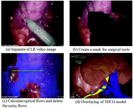
Image processing
-
2.
Convert to hue, saturation, and value images and create a mask for surgical tools based on the saturation value (Fig. 4b).
-
3.
Calculate optical flows and delete the noisy flows using the mask (Fig. 4c).
-
4.
Overlay the 3DCG model on the video image and move it with the averaged optical flow to x, y, and z translation and vertical axis rotation (Fig. 4d).
-
5.
Move the 3DCG manually using a mouse and control the transparency of each part of the 3DCG using rotary controllers (Fig. 6b).
-
6.
Output the overlaid image to the surgeon console monitor and operating room.

For accurate navigation, it is important to present necessary information to the navigation monitor in each phase of the operation because the vascular structures and organ shapes vary as the surgery progresses. Each part of the 3DCG model, including the kidney, arteries, vessels, tumors, and urinary tract, is saved separately, enabling us to control the display condition of each part independently. The status of the 3DCG model changes with respect to whether it is displaying, hiding, or making one or all parts transparent (Fig. 5).

Various status of 3DCG model
6 Navigation Procedure
We conducted 20 navigations for RALPN from November 2014 to December 2016. The position and orientation of the 3DCG model was calculated through the optical flow of the endoscopic camera images, which enabled the 3DCG model to move semi-automatically. To match the overlaid 3DCG model to organs and vessels intuitively in real time, we used three rotary and one mouse controller simultaneously (Fig. 6b). The three rotary controllers were configured for three parts: red for arteries, blue for veins, and black for the kidney, tumor, and urinary tract. The requirements of the 3DCG model appearance sequentially changed during the various phases of the RALPN surgery. To respond to these changes, we used the three rotary controllers to quickly alter the permeability of the kidney, arteries, and veins in real time.

Display of our navigation system
The projected images were simultaneously confirmed in both the surgeon’s console and the operating room monitor, which helped surgeons, nurses, and medical students to understand the surgical situation (Fig. 6c, d).
7 Case Presentation
Our support system was especially helpful in patients with small endophytic tumors or complicated vascular structures. When the tumor was small or totally endophytic, localization of the tumor and determination of its resection margin was time-consuming and laborious.
We herein present three cases in which our navigation system contributed to safe and smooth progression of RALPN.
Case 1.
The patient was a 62-year-old man with a stage 1 right renal cell carcinoma. The tumor was small and half endophytic in the renal parenchyma (Fig. 7a, b). During the surgery, the tumor could not be localized on the endoscopic image before removing the fat around the kidney (Fig. 7c), but the 3DCG navigation image appropriately showed the location and size of the tumor (Fig. 7d). This navigation image assisted the surgeons in accurately approaching the tumor.

Case 1
Case 2.
The patient was a 68-year-old man with a stage 1 left renal cell carcinoma. The tumor was small and almost totally endophytic in the renal parenchyma (Fig. 8a, b). In addition, the tumor was located on the dorsal side of the kidney, which made tumor localization difficult. The tumor could not be identified on the endoscopic image even after removing the surrounding fat (Fig. 8c), but the 3DCG navigation image appropriately showed the location, size, and depth of the tumor.

Case 2
Case 3.
The patient was a 44-year-old man with a stage 1 left renal cell carcinoma. The tumor was also totally endophytic in the renal parenchyma (Fig. 9a, b) and could not be identified on the endoscopic image even after removing the surrounding fat (Fig. 9c). Our navigation image appropriately showed the location, size, and depth of the tumor and indicated that the tumor was in contact with the urinary tract. This navigation image helped the surgeons to determine the resection line and to realize the possibility of opening the urinary tract.

Case 3
8 Conclusion
We have developed an augmented reality navigation system for RALPN. Our support system worked appropriately and was helpful to localize the tumor and determine its resection lines. Our navigation system is used under two-dimensional image registration and mainly manual control by an experienced medical doctor at present, but 3D-CT stereoscopic image registration and an automatic tracking system are currently in development. We are convinced that our system will bring significant benefits to both surgeons and patients.
References
Sengiku, A., et al.: A multi-institutional questionnaire survey on surgical treatment for a small renal mass: factors related with decision-making in indications for partial nephrectomy. Hinyokika Kiyo. 58, 665–669 (2012)
Hughes-Hallett, A., et al.: Augmented reality partial nephrectomy: examining the current status and future perspectives. Urology 83, 266–273 (2014)
Su, L.M., et al.: Augmented reality during robot-assisted laparoscopic partial nephrectomy: toward real-time 3D-CT to stereoscopic video registration. Urology 73, 896–900 (2009)
3D Slicer: http://www.slicer.org/
Koeda, M., et al.: Image overlay support with 3DCG organ model for robot-assisted laparoscopic partial nephrectomy. In: Stephanidis, C. (ed.) HCI 2016. CCIS, vol. 617, pp. 508–513. Springer, Cham (2016). doi:10.1007/978-3-319-40548-3_84
Author information
Authors and Affiliations
Corresponding author
Editor information
Editors and Affiliations
Rights and permissions
Copyright information
© 2017 Springer International Publishing AG
About this paper
Cite this paper
Sengiku, A. et al. (2017). Augmented Reality Navigation System for Robot-Assisted Laparoscopic Partial Nephrectomy. In: Marcus, A., Wang, W. (eds) Design, User Experience, and Usability: Designing Pleasurable Experiences. DUXU 2017. Lecture Notes in Computer Science(), vol 10289. Springer, Cham. https://doi.org/10.1007/978-3-319-58637-3_45
Download citation
DOI: https://doi.org/10.1007/978-3-319-58637-3_45
Published:
Publisher Name: Springer, Cham
Print ISBN: 978-3-319-58636-6
Online ISBN: 978-3-319-58637-3
eBook Packages: Computer ScienceComputer Science (R0)