
Abstract
Huge lava tubes with an approximate diameter of 65–225 m were found on the surfaces of Moon and Mars in the late 2000’s. It has been argued that the interiors of the caves are spacious, and are suitable to build artificial bases with habitable features such as constant temperature, as well as protection from both meteorites and harmful radiation. In line of the above, a number of studies which regard the soft landing mechanisms on the bottom of the lava tubes have been proposed. In this paper, aiming to extend the ability to explore arbitrary surface caves, we propose a mechanism which is able to reach the ceiling of lava tubes. The basic concept of our proposed mechanism consists of a rover connected to an oscillating sample-gatherer, wherein the rover is able to adjust the length of the rope parametrically to increase the deflection angle by considering periodic changes in the pivot, and thus to ease the collection of samples by hitting against the ceiling of the cave. Relevant simulations confirmed our theoretical observations which predict the increase of deflection angle by periodically winding and rewinding the rope according to pivotal variations. We believe the our proposed approach brings the building blocks to enable finer control of exploration mechanisms of lava tubes and narrow environments.
You have full access to this open access chapter, Download conference paper PDF
1 Introduction
A number of lava tubes with diameter of 65–140 m were found on the Moon [1], and with diameter 100–225 m, were found on Mars [2, 3]. It has been argued that the interior section of such caves spreads the vertical and the horizontal directions, possibly bringing appealing features [4, 5] such as (1) suitability for artificial bases in the moon, (2) suitability to build environments with constant temperature, and (3) protection from meteorites and radiation.
Generally speaking, exploration of lava tubes imply key tasks such as surface exploration, shape acquisition and surface sampling. A number of previous studies have regarded the exploration using rovers with active suspension [6], rovers with inflatable wheel which functions as outer wheels [7], the wired casting manipulator [8], and the wire-enable vertical hole exploration of caves [9]. Also, scientific explorations are being planned by the UZUME (Unprecedented Zipangu (Japan) Underworld of the Moon Exploration) Project.
In this paper, we propose a mechanism to enable the wire-based sampling of the ceiling of lava tubes and underground cave-like channels. Our mechanism consists of a variable-length rope connecting a rover to an oscillating mass under periodically varying length and pivot. The basic concept of our mechanism is depicted by Fig. 1, in which it becomes possible to increase the deflection angle by adjusting the length of the rope parametrically, extending the concept of variable-length pendulum to consider periodically changing pivots. Whereas variable-length pendulum [10,11,12,13,14,15] and vertically oscillating supports [15,16,17,18,19,20,21,22,23,24] have been studied widely, the study of periodic change of the pivot in the pendulum, and its application to space exploration mechanisms, has received little attention. Simulation results confirmed that the angular displacement increases by using the parametric excitation under pivotal changes. Our contributions are as follows:

Basic concept of our proposed mechanism. (a) Rover attached to a sampling actuator over a cave, (b) Basic model of parametric excitation in a pendulum with variable pivot.
-
the framework which enables the modeling of parametric excitation with periodically varying length and pivot, and
-
simulations to show the performance in terms of increase of angular displacement in the order of seconds.
Our proposed approach offers building blocks to realize a versatile class of exploration mechanisms which are not only able to gather samples from the ceilings of cave-like channels, but also able to reach the ceilings efficiently and flexibly. Our method also has the potential to be used in the narrow and harsh environments, to allow studies in space volcanism. Finally, by considering the periodic change of pivot and length explicitly, it becomes possible to model complex structures enabling finer control of oscillating behaviours.
2 Proposed Mechanism
2.1 Basic Concept
Parametric excitation implies the periodic explicit variation of a parameter in a dynamical system. For instance, in the context of a spring-mass system, the parametric excitation occurs when parameters such as mass, spring constant, or damping coefficient vary periodically. In this section, we describe the theoretical framework to allow parametric excitation of our proposed mechanism.
In the context of a swing oscillation, the equation of motion of a general pendulum that consists of a lumped mass suspended by a rigid massless rod from a pivot is derived from the angular momentum as follows:
where:
-
g is the constant due to gravity,
-
l is the length of the rigid massless rope, and
-
m is the lumped mass,
-
\(\theta \) is the angular displacement with respect to the pivot and the vertical axis.
The above definition can be simplified as follows:
In order to enable the angular displacement under conditions of change in the pivot, we allow the pendulum to have variable length according to the position of the pivot. This scheme is applicable to model mechanisms able to sample the ceiling of convex caves, as shown by Fig. 1.
For simplicity and without loss of generality, we assume the simplified model as shown by Fig. 1(b), which represents the main key features of mechanisms able to sample convex caves. Further extensions are possible by considering polygonal shapes with more than four vertices. The study of such environments are expected to be realized in a future work.

Angular displacement as a result of winding the rope. (a) Winding behaviour, and (b) Angular displacement according to the winding phase.
2.2 Piecewise Pendulum Mechanism
The key idea of our approach is to model a pendulum with variable length and pivotal variations by periodically and conditionally winding and rewinding the rope, in the presence of the ceiling of a vertical hole, which results in the excitation of the deflection angle \(\theta \), and the modeling through piecewise pendular governing equations.
In order to exemplify the above described mechanism,
-
Figure 2(a) shows examples of the phases of the Winding behaviour of a pendulum in a simplified cave model,
-
Figure 2(b) shows the angular displacement corresponding to the phases of the Winding behaviour of Fig. 2(a)
By observing Fig. 2(a) and (b) one can note the following facts:
-
the lower and upper bound of the length of the rope is \([L_{short}, L_{long}]\),
-
starting with phase 1, from the left, there exists 6 piecewise phases in the pendulum motion, in which each phase is associated with the angular displacement curves depicted by Fig. 2(b).
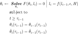
Along with the above observations, it is important to note that the angular displacement is a piecewise function of time resulting from the numerical solutions of the governing equations for each phase i, for \(i = \{1, 2, 3, ... 6\}\); and each solution of displacement curve of the phase i is subject to angular and velocity constraints with respect to the previous phase \(i-1\).
Concretely speaking, to give a clear description of the above remarks, the angular displacement of the i-th phase can be computed by solving the governing equations of the following classes:
-
(1)
Governing equations along the downward,
 (3)
(3) -
(2)
Governing equations along the trajectory,
 (4)
(4)


, where the above subscripts are defined as follows:
-
\( {\theta _{i}} \) is the angular displacement of the i-th phase with respect to the pivot and the vertical axis,
-
\( \dot{\theta _{i}} \) is the angular velocity of the i-th phase with respect to the pivot and the vertical axis,
-
\( \dot{\theta }_{i}(\tau _{i-1}) \) is the angular velocity of the i-th phase at time \(\tau _{i-1}\) with respect to the \((i-1)\)-th phase,
-
\( {l_{i}} \) is the length of the rope during the i-th phase of the pendulum,
-
\(\epsilon \) is the amount for winding and rewinding,
-
H is the height of the vertical hole (assuming a rectangular shape of the ceiling cave),
-
f: \(( {l_{i-1}} , \epsilon , H) \rightarrow {l_{i}} \) is a function mapping from the length of the rope of the previous phase \((i-1)\) to that of the current phase i, and considering the winding/rewinding \(\epsilon \) as well as the height H of the vertical hole,
-
\(\tau _{i}\) is the time a constraint on angular displacement \( {\theta _{i}} \) or angular velocity \( \dot{\theta _{i}} \) holds true.
The key difference between Eqs. 3 and 4 is the location of the ball. Whereas Eq. 3 is used to constrain the pendular motion along the downward direction, Eq. 4 is used to constrain the motion in arbitrary points along the trajectory. In line of the above, two relevant instances to compute \(\tau _{i}\) are as follows:
, where \(\tau _i\) is the time at which the pendulum reaches the downward vertical, and
where \(\tau _i\) is the time at which the pendulum reaches a point closest to the upward vertical.
Thus, by the descriptions of Eqs. 3 and 6, it is possible to allow modeling piecewise pendular displacement curves considering the continuity in time, angular displacement and angular velocity. Furthermore, by introducing the function f(.), it is possible to allow variable-length pendulums under pivotal changes.

Basic concept to compute winding time

Basic concept to compute rewinding time
2.3 Winding and Rewinding
Winding (rewinding) aims at shortening (lengthening) the length of the rope by a small constant. Because winding and rewinding are unrealizable instantaneously, we modeled the operation of the pendulum to consider the winding and rewinding time into account. Thus, in line of the above descriptions, computing the timing for winding and rewinding is computed by difference and comparison to a threshold as shown by Figs. 3 and 4, in which:
-
The initial value of \(T_{w}\) is the difference between the time to reach the downward position and the rewinding time.
-
The initial value of \(T_{rw}\) is the difference between the time to reach zero speed and the winding time.

Patterns of parametric excitation in our proposed mechanism.
2.4 Parametric Excitation Patterns
Since the basic pendulum model is unable to handle cases in which the pivot is variable, and in order to study the angular displacement under diverse winding and rewinding scenarios, we present four patterns as depicted by Fig. 5 to enable the excitatory oscillation through a variable length pendulum with pivotal changes, as follows:
Pattern 1. The first pattern in Fig. 5(a) implies the periodic winding and rewinding of the rope within the region corresponding to the shortest length of the rope. The solutions of the displacement curves are obtained by Algorithm 1, in which four piecewise displacement curves are obtained by regulating the length \( {l_{i}} \) for each phase, for \(i = \{1, 2, 3, 4\}\). Note that winding occurs just after phase 1, and rewinding occurs just after phase 2.
Pattern 2. The second pattern in Fig. 5(b) implies the periodic winding and rewinding of the rope within the region corresponding to the longest length of the rope. Here, the solutions of the displacement curves are obtained by Algorithm 2, where three piecewise displacement curves are obtained by regulating the length \( {l_{i}} \) for each phase, for \(i = \{1, 2, 3\}\). Note that winding occurs just after phase 2, and rewinding occurs just after phase 3. Also, note that phase 2 is composed of the motion from the position in the downward vertical to the position where the angular speed is zero, and viceversa.
Pattern 3. The third pattern in Fig. 5(c) implies the periodic winding and rewinding of the rope within the region corresponding to both the shortest and the longest length of the rope. The solutions of the displacement curves are obtained by Algorithm 3, in which four piecewise displacement curves are obtained by regulating the length \( {l_{i}} \) for each phase, for \(i = \{1, 2, 3, 4\}\). Note that winding occurs just after either phase 1 or phase 3, and rewinding occurs just after either phase 2 or phase 4.
Pattern 4. The fourth pattern in Fig. 5(d) implies the periodic winding and rewinding of the rope within the region corresponding to both the shortest and the longest length of the rope under sinusoidal stimuli. The solutions of the displacement curves are obtained by Algorithm 4, in which two piecewise displacement curves are obtained by regulating the length \( {l_{i}} \) for each phase, for \(i = \{1, 2\}\). Note that winding occurs as a consequence of periodic stimuli of the cosine function.


3 Results and Discussion
To evaluate the evolution of the deflection angle and the behavioural repertoire of the parametric excitation in the previously introduced winding and rewinding patterns, Fig. 6 shows the oscillation patterns of mass m assuming the longest length of the rope \(L_{long} = 2\) m, the shortest length of the rope \(l_{short} = 1\), the initial displacement \(\theta _o = 5\), the gravity constant \(g = 9.8066\), the length of wind-rewind \(\epsilon = 0.2\) m. Fine tuning the above parameters is out of the scope of this paper, and is left in our future agenda.
In Fig. 6, the following can be observed:
-
The x-axis denotes the time (in seconds), and
-
The y-axis denotes the angular displacement (in degrees)
-
The red marks at the top of Fig. 6(a)–(c) denote the oscillations which occur when the longest part of the rope achieves the maximal deflection angle.
-
Conversely, the blue marks at the bottom of Fig. 6(a)–(c) denote the oscillations which occur when the shortest part of the rope achieves the minimal deflection angle.
-
Thus, in line of the above observations, red (blue) marks indicate positive (negative) maximal (minimal) angular displacement of 90\(^\circ \) (\(-90^\circ \))
In the context of exploration of lava tubes and caves, minimal negative angular displacements are desirable since they imply the ability to reach the ceiling of the cave. Thus, for practical realizations, reaching \(-90^\circ \) with minimal time and effort is highly desirable. In line of the above requirements, by observing Fig. 6, we note the following facts:
-
In all figures, the deflection angle increases as a function of time,
-
Pattern 1 and Pattern 3 require less time to achieve a deflection angle equivalent to \(-90^\circ \) or more.
-
Among the four described patterns in Fig. 6, Pattern 4 requires more time to achieve a deflection angle equivalent to \(-60^\circ \), in which achieving minimal angular displacements depends on the amount of rewinding.
-
Among the four described patterns in Fig. 6, Pattern 1 shows the simplest operability and the ability to achieve \(-90^\circ \) in less than 60 s.
The above observations confirm that the deflection angle is increased by the parametric excitation, and that the deflection angle reaches \(-90^\circ \) when the rope becomes shortest. These results offer the possibility to control the impact to the ceiling of convex caves with finer accuracy, which is in line of our future agenda. Also, the above settings are representative to construct sampling mechanisms in small-scale caves, and in our future work, we aim at evaluating the above winding strategies in an experimental scenario.

Patterns of parametric excitation in our proposed mechanism. (Color figure online)
4 Concluding Remarks
We have proposed a mechanism to reach the ceiling of lava tubes by connecting a rover to an oscillating sample-gatherer, in which the rover is able to adjust the length of the rope parametrically to increase the deflection angle by considering periodic changes in the pivot, and thus to enable the collection of samples by hitting against the ceiling of the cave. Relevant simulations have shown that the deflection angle increases with time, and that there exists oscillating patterns archiving a deflection of \(-90^\circ \) in the order of seconds when the rope becomes shortest. Our proposed mechanism enables the building blocks to model versatile sample-gatherers of cave surfaces which perform efficiently. In our future agenda we aim to study the finer control of exploration mechanisms of lava tubes and narrow environments.
References
Haruyama, J., Hioki, K., Shirao, M., Morota, T., Hiesinger, H., van der Bogert, C.H., Miyamoto, H., Iwasaki, A., Yokota, Y., Ohtake, M., Matsunaga, T., Hara, S., Nakanotani, S., Pieters, C.M.: Possible lunar lava tube skylight observed by SELENE cameras. Geophys. Res. Lett. 36(21), 1–5 (2009)
Cushing, G.E., Titus, T.N., Wynne, J.J., Christensen, P.R.: Themis observes possible cave skylights on mars. Geophys. Res. Lett. 34(17), L17201 (2007)
Lveill, R.J., Datta, S.: Lava tubes and basaltic caves as astrobiological targets on earth and mars: a review. Planet. Space Sci. 58, 592–598 (2010). (Exploring other worlds by exploring our own: the role of terrestrial analogue studies in planetary exploration)
Robinson, M., Ashley, J., Boyd, A., Wagner, R., Speyerer, E., Hawke, B.R., Hiesinger, H., van der Bogert, C.: Confirmation of sublunarean voids and thin layering in mare deposits. Planet. Space Sci. 69, 18–27 (2012)
Blamont, J.: A roadmap to cave dwelling on the moon and mars. Adv. Space Res. 54, 2140–2149 (2014). (Lunar Science and Exploration)
Naiki, T., Kubota, T.: Study on rough terrain traversability of rover mobility system with active suspension. JSME (2010). (in Japanese)
Furutani, K.: Concept of inflatable outer wheel rover for exploration of lunar and planetary holes and subsurface caverns (special issue on innovative actuators). Int. J. Autom. Technol. 10, 584–590 (2016)
Otsuki, S., Arisumi, J.: Exploration of lunar and planetary holes and subsurface caverns: elemental technology of wired casting manipulator system for exploring planetary hole. In: Proceedings of the Space Sciences and Technology Conference (2013). (in Japanese)
Moriwa, S.: Research on lunar planet vertical hole exploration robot with wire. Research Summary, JAXA (2014)
Akulenko, L., Nesterov, S.: The stability of the equilibrium of a pendulum of variable length. J. Appl. Math. Mech. 73, 642–647 (2009)
Bartuccelli, M., Christiansen, P.L., Muto, V., Soerensen, M.P., Pedersen, N.F.: Chaotic behaviour of a pendulum with variable length. Il Nuovo Cimento B (1971–1996) 100, 229–249 (1987)
Seyranian, A.P.: Swing problem. Dokl. Phys. 49, 64–68 (2004)
Belyakov, A.O., Seyranian, A.P., Luongo, A.: Dynamics of the pendulum with periodically varying length. Phys. D 238, 1589–1597 (2009)
Pinsky, M., Zevin, A.: Oscillations of a pendulum with a periodically varying length and a model of swing. Int. J. Non-linear Mech. 34, 105–109 (1999)
Wright, J.A., Bartuccelli, M., Gentile, G.: The effects of time-dependent dissipation on the basins of attraction for the pendulum with oscillating support. Nonlinear Dyn. 77, 1377–1409 (2014)
Bardin, B., Markeyev, A.: The stability of the equilibrium of a pendulum for vertical oscillations of the point of suspension. J. Appl. Math. Mech. 59, 879–886 (1995)
Bartuccelli, M.V., Gentile, G., Georgiou, K.V.: On the dynamics of a vertically driven damped planar pendulum. Proc. R. Soc. Lond. A: Math. Phys. Eng. Sci. 457, 3007–3022 (2001)
Bartuccelli, M.V., Gentile, G., Georgiou, K.V.: On the stability of the upside-down pendulum with damping. Proc.: Math. Phys. Eng. Sci. 458(2018), 255–269 (2002)
Clifford, M.J., Bishop, S.R.: Locating oscillatory orbits of the parametrically-excited pendulum. J. Aust. Math. Soc. Ser. B Appl. Math. 37, 309–319 (1996)
Bishop, S.R., Xu, D.L., Clifford, M.J.: Flexible control of the parametrically excited pendulum. Proc. R. Soc. Lond. A: Math. Phys. Eng. Sci. 452, 1789–1806 (1996)
Capecchi, D., Bishop, S.R.: Periodic oscillations and attracting basins for a parametrically excited pendulum. Dyn. Stab. Syst. 9, 123–143 (1994)
Kim, S.Y., Hu, B.: Bifurcations and transitions to chaos in an inverted pendulum. Phys. Rev. E 58, 3028–3035 (1998)
Lenci, S., Pavlovskaia, E., Rega, G., Wiercigroch, M.: Rotating solutions and stability of parametric pendulum by perturbation method. J. Sound Vib. 310, 243–259 (2008)
Xu, X., Wiercigroch, M., Cartmell, M.: Rotating orbits of a parametrically-excited pendulum. Chaos Solitons Fract. 23, 1537–1548 (2005)
Author information
Authors and Affiliations
Corresponding author
Editor information
Editors and Affiliations
Rights and permissions
Copyright information
© 2018 Springer International Publishing AG, part of Springer Nature
About this paper

Cite this paper
Parque, V., Kumai, M., Miura, S., Miyashita, T. (2018). On Parametric Excitation for Exploration of Lava Tubes and Caves. In: Shi, Y., et al. Computational Science – ICCS 2018. ICCS 2018. Lecture Notes in Computer Science(), vol 10860. Springer, Cham. https://doi.org/10.1007/978-3-319-93698-7_36
Download citation
DOI: https://doi.org/10.1007/978-3-319-93698-7_36
Published:
Publisher Name: Springer, Cham
Print ISBN: 978-3-319-93697-0
Online ISBN: 978-3-319-93698-7
eBook Packages: Computer ScienceComputer Science (R0)