
Abstract
In our surgical navigation study, we construct a mechanical system for steadily capturing several surgical scenes by using two parallel robotic sliders and multiple vision cameras. In this paper, we first determine how to select an adequate time interval during which each camera projects a pattern to calculate depth against an organ. If multiple cameras project and receive patterns simultaneously, pattern interferences occur around the organ and, consequently, the cameras cannot capture depth images. Second, we investigate whether few or no occlusions occur in several surgical scenarios for an organ operation. Finally, we check experimentally whether distance precision in depth images is exactly maintained when a surgeon raises the camera to insert a microscope during a microsurgery. If the above functions are performed correctly, our proposed transcription algorithms for position, orientation, and shape from a real organ to its virtual polyhedron’s organ with STL-format play an active part during an actual surgery.
You have full access to this open access chapter, Download conference paper PDF
Keywords
1 Introduction
There are many methods for capturing a surgical area that includes multiple kinds of organs and/or several medical tools in an abdominal or laparoscopic surgery using different types of surgical operative procedures [1,2,3]. In the last year, we designed and constructed a prototype including one robot and one camera to capture a wider visible surgical area. The unique characteristic of this prototype is that the camera and robotic slider are connected to a surgical bed. By this connection, even though a surgeon controls the surgical bed rotationally or translationally, the relative position and orientation between the camera and surgical area are completely fixed, and therefore our proposed position, orientation, and shape transcription algorithms [4,5,6] can be directly used in real surgeries.
In this study, we extend the robotic mechanical system to eliminate many types of occlusion in a surgical area by a surgeon’s hand, head, and/or microscope. We use three types of depth image cameras: Kinect v1, Kinect v2, which were provided by Microsoft Co., and RealSense SR300 made by Intel Co. In this navigation study, we use multiple cameras numbering three or more. For this reason, we select the RealSense camera made by Intel Co. because of its small size. Multiple RealSense cameras can easily be placed at the top of the surgical area.
The Intel RealSense SR300 is based on the same principles as the PrimeSense technology used in the Microsoft Kinect v1. PrimeSense was recently purchased by Apple. The infrared structured light projector emits a structured pattern of infrared light, which is reflected back from the scene and detected by the infrared image sensor. The position of the reflected light pattern depends on the distance to the reflecting surface, determined through simple geometry. Hence, with bit of trigonometry, it is possible to reconstruct a three-dimensional (3D) scene. As shown in the explanation, a structured pattern of infrared light is projected to a target object (in our study, this is a human organ). If two or more cameras project structured patterns of infrared light simultaneously, corresponding confusion can occur, and thus, no depth images can be obtained by any of the cameras. To overcome this obstacle, we use multiple cameras whose depth images are controlled by time shearing to avoid any interference.
Subsequently, we check whether three cameras with different positions and view axes are enough to exactly capture the operations of a doctor’s hand and head in several surgical scenes (in reality, a microscope during a brain microsurgery should be added). The RealSense is formed using three components: a conventional color CMOS image sensor camera, an infrared images sensor, and an infrared light projector (the main focus of this article). There is also an image processor. If the RealSense camera and surgical area are too close, our target organ becomes too wide in the RGB color image, IR image, and depth image. As a result, our target organ is frequently obstructed by a human hand or head during a normal surgery, and/or a microscope during a microsurgery. In these cases, translation and rotation movement, deformation, and incisions in the affected surgical parts during this period are overlooked. Consequently, they cannot be copied into the virtual liver using our motion and shape transcription algorithms [7,8,9]. To overcome this problem, we use two parallel robotic sliders—single axis robot RS 1 (straight type) made by MISUMI Co.—to climb up a ring of three RealSense cameras. The precise movement of the robotic slider has a repeat positioning accuracy of 0.01 mm. The other specifications are as follows: the maximum payload mass is 6 kg / 4 kg, the vertical stroke is 50–400 mm, the maximum speed is 600 mm/s, stepping motor specifications. Because two robotic sliders are simultaneously controlled in parallel by our computer program, if the camera is returned to previous positions, the same image is obtained at that position. In addition, the SR300 has a very effective object tracking software SDK (Software Development Kit) [11]. By using this SDK, the color, infrared, and depth images always automatically focus on a target organ, even though the cameras are moved by the robotic sliders. Therefore, in this paper, we evaluate whether or not the precision of the depth image is maintained without affecting the robot movements in several types of experiments, when we use this automatic object tracking software (Fig. 1).

Our surgical measurement system with two robot sliders and three cameras.
In this paper, we explain our robotic capturing mechanism in Sect. 2. In Sect. 3, we investigate cases where there were few to no instances of damage to depth images due to interference between three cameras used simultaneously by several experiments. Furthermore, in Sect. 4, we examine cases with few to no instances of occlusion of a surgical area by surgeon’s hand or head in several experiments. In Sect. 5, we carefully evaluate which distance variation in depth images is precisely linked with the robot movement. Finally, we conclude our research in Sect. 6.
2 Experimental System
In this section, we explain our visual system for steadily capturing a surgical area. As shown in Figs. 2 and 3, even though a surgeon slides or rotates a surgical bed to maintain a wider, more comfortable view over the surgical field, the relative position and orientation between the camera and surgical field should be completely fixed. Therefore, in our navigation study, the camera and bed are directly connected (Fig. 2(a), (b)) [4,5,6]. Using a 3D liver printed by our 3D printer based on a patient’s practical liver with DICOM data, we investigate whether Microsoft Kinect v1, v2, and Intel RealSence SR300 can successfully capture three kinds of images: RGB color image, infrared image, and depth image. Appropriately, the former two cameras include a special SDK for capturing human body motions while the latter camera includes a special SDK for tracking a target object visually. For this reason, we have recently begun using the latter camera, Intel RealSence SR300.

(a) Many kinds of attachments for a surgical bed, and a mechanical frame is built by some of attachments and metal poles, (b) Two cameras are located over a 3D liver printed by our 3D printer based on a patient’s practical liver with DICOM data. In addition, RGB color, infrared, and depth images are simultaneously and adequately captured by the two cameras.

(a) One location of two cameras, metal poles, robotic slider, and computer monitor, (b) the other two cameras, metal poles, and robotic slider.
Furthermore, since there are many types of surgical operations, engineers and doctors should discuss with each other how to place the mechanical measurement system around the surgical bed. Otherwise, the mechanical measurement system might get in the way of medical work. In such a case, a surgeon, surgical assistant, anesthetist, nurse, and other medical technologists do not work well and support a surgery adequately during an operation. For this purpose, we are investigating a suitable location for the poles, robotic sliders, and computer monitor when there are several people working together around the surgical bed (Fig. 3(a), (b)). Furthermore around a surgical area, there are many kinds of organs and/or medical tools in an abdominal surgery escape from the laparoscopic and robot surgery surgeries. Therefore, different types of surgical operative procedures are interfered by multiple methods for capturing the surgical area. For this reason, the camera is moved up and down using a one-degree-of-freedom robot slider when a surgeon needs to insert the microscope between the surgical area and his head. Because one camera is vertically located along the gravity, the images always includes the surgical area through the up and down movements (Fig. 4(a), (b)). In this research, we will extend our previous mechanism and therefore capture an affected part using multiple cameras (Fig. 5(a), (b)). Using this type of multiple camera system, if a diseased part cannot be caught by initial camera images, it can be captured by other cameras. As a result, our proposed position/orientation/shape transcription algorithms become active with the support of the captured data.

(a) One camera is controlled by one robotic slider by the up and down manner, (b) camera moves up for inserting the microscope.

(a) Three cameras are steadily controlled by two robotic sliders in an up and down manner, (b) Three smaller cameras are located on a ring between two robotic sliders.
3 Few or No Instances of Interference Damage to Depth Images Between Three Cameras Used Simultaneously
The RealSense SR300 essentially calculates a depth image (the depth distance at each pixel) by triangular calculation via a structured pattern of infrared light that is projected by a projector and simultaneously received by an infrared image sensor. Therefore, if two or more structured patterns of infrared light overlap around the surface of a target organ, the reflected data are quite confusing and, consequently, none of the cameras can receive a depth image (a set of distances from each camera to the target organ).
To overcome the pattern interferences between multiple cameras, we develop software to maintain skipping frames between pattern projections of two cameras as illustrated in Fig. 6. In our research, we change the number of capturing frames (Nc) and the number of skipping frames (Ns) as follows: the pair of Nc = 4, Ns = 1–3, and the pair of Nc = 10, Ns = 3 (Fig. 6).

In our software used to control three RealSence RS300 cameras, we use time shearing with the number of capturing frames (Nc) and the number of skipping frames (Ns).
If we decrease the number of capturing frames, the response of depth image calculation by projecting and receiving the pattern increases. Therefore, an obstacle situation of a color image and its shape situation of a depth image are almost the same. Otherwise, if we increase the number of capturing frames, the response becomes slower and the obstacle situation (i.e., hand movement) in the color image and its shape situation of depth image differ from each other. Moreover, if the number of skipping frames is reduced, a degree of interference frequently occurs and, as a result, the present camera cannot capture the depth image.
-
Nc = 4 and Ns = 1: pattern projecting and receiving frequently interfere with each other, and, consequently, a depth image frequently cannot be obtained (Fig. 8).
-
Nc = 4 and Ns = 2: pattern projecting and receiving rarely interfere with each other, and, consequently, a depth image rarely cannot be obtained (Fig. 7).
Fig. 7. 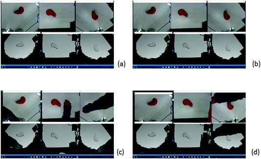
If we set Nc = 4 and Ns = 2, a depth image rarely cannot be obtained as in (a) and (b), but the depth image cannot quickly follow the color image as in (c) and (d).
-
Nc = 4 and Ns = 3: pattern projecting and receiving do not interfere with each other, and consequently depth image can always be obtained (Fig. 9).

It is important to note that this may change depending on the distance to the camera.
4 Few or No Instances of Occlusion of a Surgical Area by a Surgeon’s Hand or Head
In this section, using our system during several surgical operations, which are simulated with typical participants, we meticulously check if at least one of the three cameras captures a surgical area. As shown in Figs. 7, 8, and 9, if a typical person watches and simultaneously operates a 3D liver while capturing with three RealSense cameras, at least one camera always captures the 3D liver and thus precisely provides color and depth images.

If we set Nc = 4 and Ns = 1, a depth image frequently cannot be obtained as in (a) and (b), but the depth image quickly follows the movement of the hand in the color image as in (c) and (d).

If we set Nc = 4 and Ns = 3, a depth image can always be obtained as in (a) and (b), but the delay (difference) between the depth image and the color image becomes larger as in (c) and (d).
One in a million, if all cameras cannot capture any 3D liver, a human controls two robotic sliders in order to climb up the ring of three RealSense cameras. By this movement, each camera has a wider view and, consequently, at least one of the three cameras can capture the 3D liver (Fig. 10).

If we climb up the ring of three RealSense cameras at (b) and (c) through an automatic program, the camera view with color and depth images becomes wider from (a) to (d).
5 Distance Precision Variation of Depth Images Using Robotic Sliders
In our navigation study, we use the RealSense SR300 and its Tracking SDK [10]. The SDK is explained as follows: The Metaio 3D-object-tracking module provides optical-based tracking techniques that can detect and track known or unknown objects in a video sequence or scene. The Metaio Toolbox is provided to train, create, and edit 3D models that can be passed to various object detection and tracking algorithms.
Table 1 provides an overview of various tracking techniques and how they can be configured [10]. First and foremost, the following steps explain the operation concretely. 1. Detect feature points on the screen. 2. Register feature points instead of markers. 3. Compute the movement of the screen based on the center coordinates of the feature points. In our navigation study, we use Marker Tracking provided by the RealSense SDK for tracking. The provided Marker Tracking occurs as follows:
In order to scan objects that have a simple symmetric shape, such as cylinders or spheres, enable the optional marker-based tracking system and use the marker according to the following instructions.
-
1.
Print the marker in color (not black and white), making sure that you turn off any scaling (e.g., Fit to Page) in print options; print at actual size.
-
2.
Place the printed marker on a flat surface, like a tabletop or floor. It might be helpful to tape the marker down.
-
3.
Place your object on the marker, centering it as best as you can within the dashed circle.
The object must not cover too much of the marker; the camera should be able to see at least three of the four long red and blue edges at all times. The majority of the object should lie within the dashed circle.
-
4.
Start scanning, making sure object stays in place on marker. Move camera around the object and marker, making sure the marker stays in view the whole time.
It is possible to leave the camera stationary and rotate the marker by hand (like a turntable), as long as your hand stays near the edges so as not to be visible to the camera, and the object does not move relative to the marker during the scan process. In this case, it might be helpful to attach the marker to a rigid board and also attach the object to the marker.
-
5.
If tracking gets lost, go back to a previously scanned area and hold still for a few seconds; if tracking does not resume, then restart the scan.
Even though the ring of three cameras is moving up or down, the object tracking always keeps the 3D liver at the center of the images. Further, robot movement can be precisely cancelled at each distance of the depth image. In other words, several types of depth images obtained by the robot control are precisely normalized in relation to depth distance. These properties are experimentally investigated for capturing 30 points around a 3D liver (Fig. 11).

(a) Camera No.1 without object tracking captures depths at 30 points as shown in Fig. 9. Then, we calculate their average and indicate the variances by red colored bars while the ring of three cameras is moved up or down by the robotic slider’s movement, which are colored green, blue, red, light green, and orange. The difference in robot movement deviates significantly from the difference in depth change. (b) Camera No. 1 with the object tracking captures depths at 30 points. Then, we calculate their average and indicate the variances by red colored bars while the ring of three cameras is moved up or down by the robotic slider’s movement, which are colored green, blue, red, light green, and orange. The difference in robot movement slightly differs from the difference in depth change (Color figure online).
As shown in Fig. 12(a), we describe experimental results captured by camera No. 1 without object tracking for 30 points around a 3D liver. Subsequently, we calculate their average and indicate the variances by red colored bars while the camera ring is moved up or down by the robotic sliders, whose invariable distances are colored green, blue, red, light green, and orange. In Fig. 12(a), the difference in robot movement deviates significantly from the difference in depth change.

We move up or down the ring of three RealSense RS300 cameras by using two robotic sliders in parallel, and then capture 30 depths at 30 points around a 3D liver. Then, by evaluating these variations of depths, we check whether the robot movements are adequately cancelled in the sequence of 30 depths.
As illustrated in Fig. 12(b), camera No. 1 with object tracking captures depths at 30 points. We then calculate their average and indicate the variances by red colored bars while the ring of three cameras is moved up or down by the robotic slider’s movement, colored green, blue, red, light green, and orange. The difference in robot movement slightly differs from the difference in depth change. The reason for this result is that the data captured at point 1 is not good data, as shown in Fig. 13(a).

(a), (b), (c), (d) Depth variance at points 1, 10, 20, 30 captured by camera No. 1 with the object tracking are explained. Point 1’s data is quite bad and this leads to the difference in robot movement slightly differing from the difference in depth change, as shown in Fig. 12(b).
In addition, as shown in Fig. 14(a), we describe experimental results captured by camera No. 2 without object tracking for 30 points around a 3D liver. After that, we calculate their average and indicate the variances by red colored bars while the camera ring is moved up or down by the robotic sliders whose depth distances are colored green, blue, red, light green, and orange. The difference of robot movement extremely differs from the difference of depth change.

(a) Camera No.2 without object tracking captures depths at 30 points. Then, we calculate their average and indicate the variances while the ring of three cameras is climbed up or down by the robotic slider’s movement. The difference of robot movement extremely differs from the difference of depth change. (b) Camera No.2 with object tracking captures depths at 30 points. Then, we calculate their average and indicate the variances while the ring of three cameras is climbed up or down by the robot movement. The difference of robot movement is coincident with the difference of depth change.
Moreover, in Figs. 14(b), camera No.2 with the object tracking captures depths at 30 points. Then, we calculate their average and indicate the variances by red colored bars while the ring of three cameras is climbed up or down by the movements of robotic slider, which are colored green, blue, red, light green, and orange. The difference in robot movement is equivalent to the difference in depth change. The reason for this result is that all data captured at all points are quite good, as shown in Fig. 15.

(a),(b),(c),(d) Depth variance at the points 1, 10, 20, 30 captured by the camera No.1 with the object tracking are explained, respectively. All point data are very good, and, consequently, the difference of robot movement coincides with the difference of depth change as shown in Fig. 14(b).
Furthermore, in Fig. 16(a), we describe the experimental result captured by camera No. 3 without object tracking for 30 points around a 3D liver. We then calculate their average and indicate the variances while the camera ring is moved up or down by the robotic sliders. The difference in robot movement deviates from the difference in depth change.

(a) Camera No. 3 without object tracking captures depths at 30 points. Then, we calculate their average and indicate the variances while the ring of three cameras is moved up or down by the robotic slider’s movement. The difference in robot movement varies significantly from the difference in depth change. (b) Camera No. 3 with object tracking captures depths at 30 points. Then, we calculate their average and indicate the variances while the ring of three cameras is moved up or down by the robot movement. The difference in robot movement concurs with the difference in depth change.
Further, in Figs. 16(b), camera No. 3 with object tracking captures depths at 30 points. We then calculate their average and indicate the variances while the ring of three cameras is moved up or down by the robotic slider’s movement. The difference in robot movement concurs with the difference of depth change. The reason for this result is that there is no bad data captured at any point, as shown in Fig. 17.

(a), (b), (c), (d) Depth variances at points 1, 10, 20, and 30 captured by camera No. 1 with object tracking are explained. All the point data are very good and, consequently, the difference in robot movement coincides with the difference in depth change, as shown in Fig. 16(b).
6 Conclusions
In this research, we focus on two functions: (1) At least one of three cameras can capture a surgical area by using three cameras placed at different positions and pointing in different directions. (2) When a doctor inserts a microscope between multiple cameras and a surgery area for microsurgery, the camera set climbs up and down using our robotic sliders. In this case, even though the distance from each camera to a 3D liver is changed by the robot movement, depth distance captured by the camera is synchronously changed. Since the two functions are firmly maintained, our position/orientation/shape following algorithms are always available in our navigation study.
References
Logan, W.C., Prashanth, D., William, C.C., Benoit, M.D., Robert, L.G., Michael, I.M.: Organ surface deformation measurement and analysis in open hepatic surgery: Method and preliminary results from 12 clinical cases. IEEE Trans. Biomed. Eng. 58(8), 2280–2289 (2011). doi:10.1109/TBME.2011.2146782
Xu, A., Zhu, J.F., Zhang, D.: Development of a measurement system for laparoendoscopic single-site surgery: Reliability and repeatability of digital image correlation for measurement of surface deformations in SILS port. JSLS 18(3) (2014). doi:10.4293/JSLS.2014.00267, PMCID: PMC4154418
Kang, N., Lee, M.W., Rhee, T.: Simulating liver deformation during respiration using sparse local features. IEEE Comput. Graph. Appl. 32(5), 29–38 (2012). doi:10.1109/MCG.2012.65
Watanabe, K., Kayaki, M., Mizushino, K., Nonaka, M., Noborio, H.: A mechanical system directly attaching beside a surgical bed for measuring surgical area precisely by depth camera. In: Proceedings of the 10th MedViz Conference and the 6th Eurographics Workshop on Visual Computing for Biology and Medicine (EG VCBM), Bergen, Norway, pp. 105–108, 7–9 September (2016). ISBN:978-82-998920-7-0 (Printed), ISBN:978-82-998920-8-7 (Electronic)
Watanabe, K., Kayaki, M., Mizushino, K., Nonaka, M., Noborio, H.: Brain shift simulation controlled by directly captured surface points. In: Proceedings of the 38th Annual International Conference of the IEEE Engineering in Medicine and Biology Society (EMBC 2016), Category: Late Breaking Research Posters, Theme: BioMedical Imaging and Image Processing, Sessions: Ignite_Theme 2_Fr2, Poster Session III, Orlando Florida USA, 16–20 August (2016)
Watanabe, K., Kayaki, M., Mizushino, K., Nonaka, M., Noborio, H.: Capturing a brain shift directly by the depth camera kinect v2. In: Proceedings of the 38th Annual International Conference of the IEEE Engineering in Medicine and Biology Society (EMBC 2016), Category: Late Breaking Research Posters, Theme: Computational Systems & Synthetic Biology; Multiscale Modeling, Sessions: Ignite_Theme 4_Fr1, Poster Session II, Orlando Florida USA, August 16–20 (2016)
Noborio, H., et al.: Tracking a real liver using a virtual liver and an experimental evaluation with kinect v2. In: Ortuño, F., Rojas, I. (eds.) IWBBIO 2016. LNCS, vol. 9656, pp. 149–162. Springer, Cham (2016). doi:10.1007/978-3-319-31744-1_14
Noborio, H., et al.: Depth image matching algorithm for deforming and cutting a virtual liver via its real liver image captured using kinect v2. In: Ortuño, F., Rojas, I. (eds.) IWBBIO 2016. LNCS, vol. 9656, pp. 196–205. Springer, Cham (2016). doi:10.1007/978-3-319-31744-1_18
Noborio, H., Watanabe, K., Yagi, M., Ida, Y., Nankaku, S., Onishi, K., Koeda, M., Kon, M., Matsui, K., Kaibori, M.: Experimental results of 2D depth-depth matching algorithm based on depth camera kinect v1. J. Bioinform. Neurosci. 1(1), 38–44 (2015)
Noborio, H., Watanabe, K., Yagi, M., Ida, Y., Onishi, K., Koeda, M., Nankaku, S., Matsui, K., Kon, M., Kaibori, M.: Image-based initial position/orientation adjustment system between real and virtual livers. Jurnal Teknologi, Med. Eng. 77(6), 41–45 (2015). doi:10.11113/jt.v77.6225, Penerbit UTM Press, E-ISSN: 2180-3722
Intel® RealSense™ SDK 2016 R2 Reference Manual: Object Tracking, API Version 10.0 (2016)
Acknowledgments
This study was supported in part by 2014 Grants-in-Aid for Scientific Research (No. JP26289069) from the Ministry of Education, Culture, Sports, Science, and Technology, Japan. Further support was provided by the 2014 Cooperation Research Fund from the Graduate School at Osaka Electro- Communication University.
Author information
Authors and Affiliations
Corresponding author
Editor information
Editors and Affiliations
Rights and permissions
Copyright information
© 2017 Springer International Publishing AG
About this paper
Cite this paper
Nonaka, M., Watanabe, K., Noborio, H., Kayaki, M., Mizushino, K. (2017). Capturing a Surgical Area Using Multiple Depth Cameras Mounted on a Robotic Mechanical System. In: Marcus, A., Wang, W. (eds) Design, User Experience, and Usability: Designing Pleasurable Experiences. DUXU 2017. Lecture Notes in Computer Science(), vol 10289. Springer, Cham. https://doi.org/10.1007/978-3-319-58637-3_42
Download citation
DOI: https://doi.org/10.1007/978-3-319-58637-3_42
Published:
Publisher Name: Springer, Cham
Print ISBN: 978-3-319-58636-6
Online ISBN: 978-3-319-58637-3
eBook Packages: Computer ScienceComputer Science (R0)