Abstract
Software Product Line Engineering (SPLE) deals with developing artifacts that capture the common and variable aspects of software product families. Domain models are one kind of such artifacts. Being developed in early stages, domain models need to specify commonality and variability and guide the reuse of the artifacts in particular software products. Although different modeling methods have been proposed to manage and support these activities, the assessment of these methods is still in an inceptive stage. In this work, we examined the comprehensibility of domain models specified in ADOM, a UML-based SPLE method. In particular, we conducted a controlled experiment in which 116 undergraduate students were required to answer comprehension questions regarding a domain model that was equipped with explicit reuse guidance and/or variability specification. We found that explicit specification of reuse guidance within the domain model helped understand the model, whereas explicit specification of variability increased comprehensibility only to a limited extent. Explicit specification of both reuse guidance and variability often provided intermediate results, namely, results that were better than specification of variability without reuse guidance, but worse than specification of reuse guidance without variability. All these results were perceived in different UML diagram types, namely, use case, class, and sequence diagrams and for different commonality-, variability-, and reuse-related aspects.


Notes
The experimental material is accessible at: http://mis.hevra.haifa.ac.il/~iris/research/SPLEeval/ComADOM.htm#reusability.
The questionnaire was given to the participants in their mother tongue. Thus, Appendix C is actually the translation of the questions into English.
We adopted the more conservative correction approach of Bonferroni for performing multiple comparisons. As we had 6 comparisons, we looked at a significance level lower than 0.0083 (i.e., 0.05/6).
r is the size effect.
References
Ahmed F, Capretz LF (2008) The software product line architecture: an empirical investigation of key process activities. Inf Softw Technol 50:1098–1113
Anastasopoulos M, Gracek C (2001) Implementing product line variabilities. ACM SIGSOFT Softw Eng Notes 26(3):109–117
Bachmann F, Clements PC (2005) Variability in software product lines. Technical Report CMU/SEI-2005-TR-012, available online at http://www.sei.cmu.edu/library/abstracts/reports/05tr012.cfm, Accessed 9 September 2012
Bachmann F, Goedicke M, Leite J, Nord R, Pohl K, Ramesh B, Vilbig A (2004) A meta-model for representing variability in product family development. In: van der Linden F (ed): PFE’2003, LNCS 3014, pp. 66–80.
Bagheri E, Dasevic G (2011) Assessing the maintainability of software product line feature models using structural metrics. Software Quality Journal, Springer, doi:10.1007/s11219-010-9127-2
Becker M (2003) Towards a general model of variability in product families. In: Proceedings of the Software Variability Management Workshop, University of Groningen, The Netherlands
Bragança A, Machado RJ (2006) Extending UML 2.0 metamodel for complementary usages of the «extend» relationship within use case variability specification. In: Proceedings of the 10th International Software Product Line Conference (SPLC), pp 123–130
Bühne S, Halmans G, Pohl K (2003) Modeling dependencies between variation points in use case diagrams. In: Proceedings of the 9th international workshop on requirements engineering – Foundation for Software Quality (REFSQ’03), pp 59–70
Burton-Jones A, Wand Y, Weber R (2009) Guidelines for empirical evaluations of conceptual modeling grammars. J Assoc Inf Syst 10:495–532
Chen L, Babar MA (2011) A systematic review of evaluation of variability management approaches in software product lines. Inf Softw Technol 53:344–362
Clauß M (2001) Generic Modeling using UML extensions for variability. In: Proceedings of OOPSLA Workshop on Domain-specific Visual Languages, pp 11–18
Clements P, Northrop L (2001) Software product lines: practices and patterns. Addison-Wesley Professional. Part of the SEI Series in Software Engineering series
Clotet R, Dhungana D, Franch X, Grunbacher P, Lopez L, Marco J, Seyff N (2008) Dealing with changes in service-oriented computing through integrated goal and variability modelling. In: Proceeding of the second International Workshop on Variability Modelling of Software-intensive Systems (VaMoS’2008), pp 43–52
Coplien J, Hoffman D, Weiss D (1998) Commonality and variability in software engineering. IEEE Softw 15(6):37–45
Coriat M, Jourdan J, Fabien B (2000) The SPLIT method: building product lines for software-intensive systems. In: Proceedings of the first conference on Software Product Lines: experience and research directions: experience and research directions (SPLC’2000), pp 147–166
Czarnecki K, Kim CHP (2005) Cardinality-based feature modeling and constraints: a progress report. OOPSLA Workshop on Software Factories
Denger C, Kolb R (2006) Testing and inspecting reusable product line components: first empirical results. In: Proceedings of the 2006 ACM/IEEE International Symposium on Empirical Software Engineering, ACM, pp 184–193
Djebbi O, Salinesi C (2006) Criteria for comparing requirements variability modeling notations for product lines. The Fourth International Workshop on Comparative Evaluation in Requirements Engineering (CERE’06), in conjunction with RE’06
Gomaa H (2004) Designing software product lines with UML: from use cases to pattern-based software architectures, Addison-Wesley Professional
Gomaa H, Shin ME (2002) Multiple-view meta-modeling of software product lines. In: Proceedings of the 8th IEEE International Conference on Engineering of Complex Computer Systems (ICECCS’02), pp 238–246
Halmans G, Pohl K (2003) Communicating the variability of a software-product family to customers. Softw Syst Model 2(1):15–36
Halmans G, Pohl K, Sikora E (2008) Documenting application-specific adaptations in software product line engineering. In: Proceedings of the 20th International Conference on Advanced Information Systems Engineering (CAiSE’2008), LNCS 5074, pp 109–123
Haugen Ø, Møller-Pedersen B, Oldevik J (2005) Comparison of system family modeling approaches. In: Proceeding of Software Product Lines Conference (SPLC’2005), LNCS 3714, pp 102–112
Haugen Ø, Møller-Pedersen B, Oldevik J, Olsen GK, Svendsen A (2008) Adding standardized variability to domain specific languages. In: Proceeding of the 12th International Software Product Line Conference (SPLC), IEEE Computer Society, pp 139–148
Jacobson I, Griss M, Jonsson P (1997) Software reuse: architecture, process and organization for business success. ACM Press, New York
John I, Muthig D (2002) Tailoring use cases for product line modeling. In: Proceedings of the International Workshop on Requirements Engineering for Product Lines (REPL’02), pp 26–32
Kim J, Hahn J, Hahn H (2000) How do we understand a system with (so) many diagrams? cognitive integration processes in diagrammatic reasoning. Inf Syst Res 11(3):284–303
Kim J, Kim M, Yang H, Park S (2004) A method and tool support for variant requirements analysis: goal and scenario based approach. In: Proceedings of the 11th Asia-Pacific Software Engineering Conference (APSEC’04), pp 168–175
Kitchenham BA, Lawrence S, Lesley P, Pickard M, Jones PW, Hoaglin DC, Emam KE (2002) Preliminary guidelines for empirical research. IEEE Trans Softw Eng 28(8):721–734
Korherr B, List B (2007) A UML 2 profile for variability models and their dependency to business processes. In: Proceedings of the 18th International Conference on Database and Expert Systems Applications, pp 829–834
Lazilha FR, Barroca L, Alves de Oliveira E, de Souza Gimenes IM (2004) A component-based product line for workflow management systems. The IEEE Conference on Information Reuse and Integration, pp 112–119
Maßen T, Lichter H (2002) Modeling variability by UML use case diagrams. In: Proceedings of the International Workshop on Requirements Engineering for Product Lines (REPL’02), pp 19–25
Matinlassi M (2004) Comparison of software product line architecture design methods: comparison of software product line architecture design methods: COPA, FAST, FORM, KobrA and QADA. In: Proceedings of the 26th International Conference on Software Engineering (ICSE’04), pp 127–136
Moody D (2009) The physics of notations: toward a scientific basis for constructing visual notations in software engineering. IEEE Trans Softw Eng 35(6):756–779
Moon M, Yeom K, Seok Chae H (2005) An approach to developing domain requirements as a core asset based on commonality and variability analysis in a product line. IEEE Trans Softw Eng 31(7):551–569
Morisio M, Travassos G, Stark M (2000) Extending UML to support domain analysis. In: Proceedings of the 15th IEEE International Conference on Automated Software Engineering (ASE’00), pp 321–324
Nugroho A (2009) Level of detail in UML models and its impact on model comprehension: a controlled experiment. Information and Software Technology – special issue on Quality of UML Models, 51(12):1670–1685
Oliveira Junior EA, Gimenes IMS, Huzita EHM, Maldonado JC (2005) A variability management process for software products lines. In: Proceedings of the 2005 conference of the Centre for Advanced Studies on Collaborative research, Toranto, Ontario, Canada, pp 225–241
Oliveira Junior EA, Gimenes IMS, Maldonado JC (2010) Systematic management of variability in UML-based software product lines. J Univ Comput Sci 16(17):2374–2393
Pohl K, Böckle G, van der Linden F (2005) Software product line engineering: foundations, principles, and techniques. Springer, Berlin
Ramesh V, Topi H (2002) Human factors research on data modeling: a review of prior research, an extended framework and future research directions. J Database Manag 13(2):3–19
Reinhartz-Berger I, Sturm A (2008) Enhancing UML models: a domain analysis approach. J Database Manag 19(1):74–94
Reinhartz-Berger I, Sturm A (2009) Utilizing domain models for application design and validation. Inf Softw Technol 51(8):1275–1289
Reinhartz-Berger I, Tsoury A (2011) Experimenting with the comprehension of feature-oriented and UML-based core assets. In: Halpin T et al. (eds): BPMDS 2011 and EMMSAD 2011, LNBIP 81, pp 468–482
Reinhartz-Berger I, Tsoury A (2011) Specification and utilization of core assets: feature-oriented vs. UML-based methods. In: De Troyer O et al. (eds): ER 2011 Workshops, LNCS 6999, pp 302–311
Riebisch M, Böllert K, Streitferdt D, Franczyk B, Ilmenau TG (2000) Extending the UML to model system families. In: Proceedings of the 5th International Conference on Integrated Design and Process Technology (IDPT)
Ripon SH, Talukder KH, Molla KI (2003) Modelling variability for system families. Malays J Comput Sci 16(1):37–46
Robak S, Franczyk B, Politowicz K (2002) Extending the UML for modeling variability for system families. Int J Appl Math Comput Sci 12(2):285–298
Salicki S, Farcet N (2002) Expression and usage of the variability in the software product lines. In: van der Linden F (ed): PFE-4 2001, LNCS 2290, pp 304–318
Schmid K, Rabiser R, Grünbacher P (2011) A comparison of decision modeling approaches in product lines. In: Proceedings of the 5th Workshop on Variability Modeling of Software-Intensive Systems (VaMoS’2011), pp 119–126
Shanks G, Nuredini J, Tobin D, Moody D, Weber R (2003) Representing things and properties in conceptual modeling: an empirical evaluation. In: Proceedings of the 11th European Conference on Information Systems, pp 1775–1785
Siau K (2004) Informational and computational equivalence in comparing information modeling methods. J Database Manag 15(1):73–86
Siau K, Cao Q (2001) Unified Modeling Language (UML) – a complexity analysis. J Database Manag 12(1):26–34
Sinnema M, Deelstra S (2008) Industrial validation of COVAMOF. J Syst Softw 81(4):584–600
Sinnema M, Deelstraa S (2007) Classifying variability modeling techniques. Inf Softw Technol 49(7):717–739
Song IY (2001) Developing sequence diagrams in UML. In: Proceedings of the International Conference on Conceptual Modeling (ER’2001), LNCS 2224, pp 368–382
Sun C, Rossing R, Sinnema M, Bulanov P, Aiello M (2010) Modeling and managing the variability of web service-based systems. J Syst Softw 83(3):502–516
Svahnberg M, Van Gurp J, Bosch J (2005) A taxonomy of variability realization techniques. Software–Practice and Experience 35 (8): 705–754.
Webber D, Gomaa H (2004) Modeling variability in software product lines with variation point model. Sci Comput Program 53:305–331
Weiler T (2003) Modelling architectural variability for software product lines. In: Proceedings of the Software Variability Management workshop, van Grop, Bosch (eds), pp 53–61
Witte RS, Witte JS (2009) Statistics. Wiley
Wohlin C, Runeson P, Höst M, Ohlsson MC, Regnell B, Wesslen A (2000) Experimentation in software engineering – an introduction. Kluwer Academic Publishers, Boston
Ziadi T, Jézéquel JM (2006) Software product line engineering with the UML: deriving products. In: Käkölä T, Dueñas JC (eds), Software Product Lines–Research Issues in Engineering and Management, Springer, pp 557–588
Ziadi T, Hélouët L, Jézéquel JM (2004) Towards a UML profile for software product lines. In: Proceeding of Software Product-Family Engineering (PFE’2004), LNCS 3014, pp 129–139
Author information
Authors and Affiliations
Corresponding author
Additional information
Editor: Murray Wood
Appendices
Appendix A: Comparison of UML-based SPLE Methods
Appendix B: The Formalism of the ADOM Method
Next we formally define the ADOM method.
The elements of UML are classified into three categories: dependent, relational, and first order elements.
Definition 1
Dependent elements are elements that depend on other elements in the model such that the omission of the dependees from the model implies the omission of the dependent elements.
Examples of dependent elements are attributes and operations in UML class diagrams that depend on their owning classes and sub-packages that depend on their owning packages.
Definition 2
Relational elements are explicit binary (directional) relationships between pairs of elements.
Examples of relational elements are associations in UML class diagrams and messages in UML sequence diagrams. Note that all kinds of relationships in UML are binary or can be mapped to binary relations.
Definition 3
First order elements are elements which are not relational nor dependent in the model.
All kinds of elements can be associated with the «multiplicity» stereotype which is defined next.
Definition 4
The «multiplicity min=n max=m» stereotype, which can be associated to any element in the domain model, specifies the range of elements in the application artifact that can be classified as the same domain element. The two tagged values, min and max, are used for defining the lowest and upper-most boundaries of that range.
The meanings of the «multiplicity» stereotype are slightly different according to the element types: first order, dependent or relational elements. The multiplicity stereotype of a dependent element specifies the range of times this domain element can be used in any dependee of a software product in that line. Specifying, for example, the multiplicity of an attribute A of class C as «multiplicity min=1 max=*» implies that between 1 to ∞ attributes of type A have to be included in each class of type C in a certain product in the line.
The multiplicity stereotype of a relational element specifies the range of times this domain element can appear, connecting the relevant source and target in any product of the line. Specifying, for example, the multiplicity of an association r between class A and class B as «multiplicity min=1 max=*» implies that in any product in the line in which both A and B appear, each appearance of A is connected to at least one appearance of B via associations of type r, and vice versa.
Lastly, the multiplicity stereotype of first order elements specifies the range of times the relevant domain elements can appear in any product of that line.
Note that any combination of the multiplicity stereotypes is feasible. For example, a mandatory relational element can connect two optional elements, implying that if the two elements appear in a certain product, then the relational element must connect them. Similarly, a mandatory dependent element may reside within an optional element, implying that if the dependee appears in a certain product, then the dependent element must appear too.
Optional elements can be connected via «requires» and «excludes» dependencies in order to constrain larger configurations.
Definition 5
Let A and B be two optional elements in a domain model. A «requires» B implies that if A appears in a particular product, then B should appear too. A «excludes» B implies that if A is included in a particular product, then B should not appear. Furthermore, in order to avoid redundancy or non-feasible models, the following constraints must hold:
-
C1.
If A requires B, then A.multiplicity.min=0 and B.multiplicity.min=0.
-
C2.
If A excludes B, then A.multiplicity.min=0 and B.multiplicity.min=0.
The following definitions refer to the specification of variability in ADOM.
Definition 6
The «variation_point open=true/false card=m..n» stereotype indicates places in which variability can be introduced. The variation point can be open (open=true), meaning that product-specific variants not specified in the domain models can be added at this point or closed (open=false), i.e., addition of product-specific variants that are not specified in the domain models is not allowed at this point. The card tagged value indicates the minimal (m) and maximal (n) numbers of variants the can be selected for this variation point. The following constraints must hold with respect to variation points:
-
C3.
If m = 0, then open=true.
-
C4.
If open=false, then m ≥ 1.
Definition 7
The «variant vp=name» stereotype is used for indicating a possible way to realize variability in a certain variation point. vp indicates the name of the variation point in case an explicit inheritance relationship between the variant and variation point cannot be specified (in the case of non-classifiers). The following constraints must hold with respect to variants and their associated variation points:
-
C5.
The multiplicity of a variant (v) can be the same or more restricted than the multiplicity of the relevant variation point (vp). Formally expressed as: vp.multiplicity.min ≤ v.multiplicity.min ≤ v.multiplicity.max ≤ vp.multiplicity.max.
Note that no restriction exists between the cardinality values and the multiplicity values of both variants and variation points, as cardinality refers to the selection of variants in a single occurrence of the variation point in a software product, while multiplicity refers to the general number of occurrences of the variation point or the variant in the whole product.
Finally, the reuse guidance is specified in ADOM using the «reuse» stereotype, defined below.
Definition 8
The «reuse mechanism=name» stereotype is used to guide the usage of a domain element in various products in the line. The mechanism tagged value specifies the applicable reuse mechanism. In the current work we refer only to the following values: s—usage (a representative of the selection reuse mechanisms), e—extension (a representative of the substitution reuse mechanisms), and se—not constrained (i.e., either usage or extension). The following constraints must hold with respect to the reuse guidance of variation points and the associated variants:
-
C6.
The reuse mechanisms of a variant (v) can be the same or more restricted than the reuse mechanisms of the relevant variation point (vp), namely:
-
1.
If vp.reuse.mechanism = ‘se’, then v.reuse.mechanism∈{‘s’, ‘e’, ‘se’}.
-
2.
If vp.reuse.mechanism = ‘e’, then v.reuse.mechanism = ‘e’.
-
3.
If vp.reuse.mechanism = ‘s’, then v.reuse.mechanism = ‘s’.
Note that there are no constraints on the reuse mechanisms of dependees and dependent elements or on the reuse mechanisms of relational elements and their associated source and target elements, as these are separate elements whose reuse may differ.
Appendix C: The Experiment Questionnaire
Below are the models and translation of the 15 comprehension questions given to the ‘reuse and variability’ group. The questions of the other three groups were identical to the questions provided here, while the different models can be found with the experimental material at http://mis.hevra.haifa.ac.il/~iris/research/SPLEeval/ComADOM.htm#reusability.
-
1.
A product in the CICO line may include an item reservation. In this case, only borrowers and workers can perform this activity that cannot undergo any refinement or extension.
-
2.
Each product in the CICO line must interact with either private borrowers or cooperation borrowers.
-
3.
In case a product in the CICO line has the functionality of “Check-In with Fee Calculation”, then it must include the functionality of “Calculate Fee” too.
-
4.
In the CICO line there might be products which will not include explicit reference to fee calculation (through use cases, such as “Check-In with Fee Calculation”, “Check-In with possible Fee Calculation” or “Check-In without Fee Calculation”).
-
5.
In the CICO line there might be products that support both Lending Policy and Waiting Lists.
-
6.
Products within the CICO line may include associations of type “handle” between Borrower and Lending that are not of type “manage” nor of type “perform”.
-
7.
Products in the CICO line may include Items with no loan fee information nor location details.
-
8.
An Item in a CICO product may have both loan fee information and location details.
-
9.
A product in the CICO line may include a virtual item that exhibits a method for calculating reservation fees which receives the actual lending period as a parameter.
-
10.
In each product in the CICO line, a class of type Lending should be related to exactly one class of type Borrower.
-
11.
In each product in the CICO line, if a class of type Borrower is associated to a class of type Lending with an association of type “manage”, then there should be an association class of type “managing” which documents the changes.
-
12.
There might be a product in the CICO line in which a controller object will not be involved in a scenario of Check-Out Item to Borrower.
-
13.
In a Check-Out scenario of a CICO product, one can borrow both virtual and physical items.
-
14.
In a CICO product, a controller object can send messages other than getItemDetails and verifyStatus to an Item object while executing the scenario named “Check-Out Item to Borrower without Waiting List”.
-
15.
It is possible that in a CICO product that does not define a waiting list, the combined fragment named “Check Out-Item to Borrower with Waiting List” will be executed while performing Check-Out.
Fig. 11 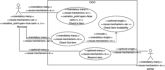
CICO model: the top level use case diagram
Fig. 12 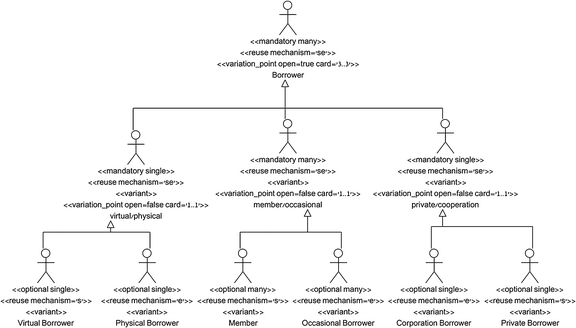
CICO model: the Borrower variation point
Fig. 13 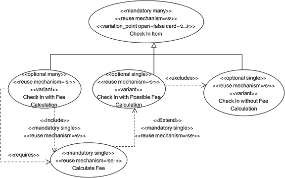
CICO model: the Check In Item variation point
Fig. 14 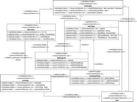
CICO model: the top level class diagram
Fig. 15 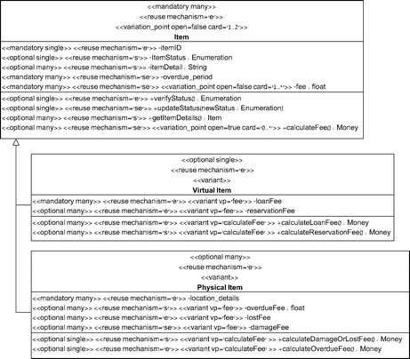
CICO model: the Item variation point
Fig. 16 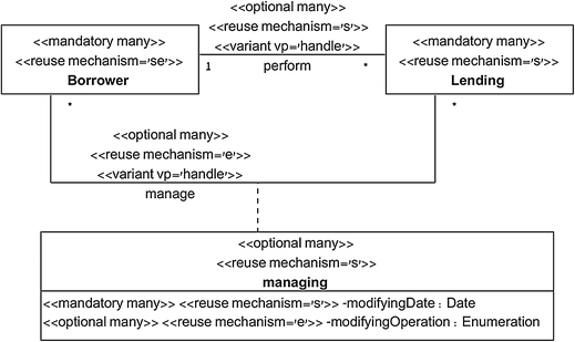
CICO model: the Handle variation point
Fig. 17 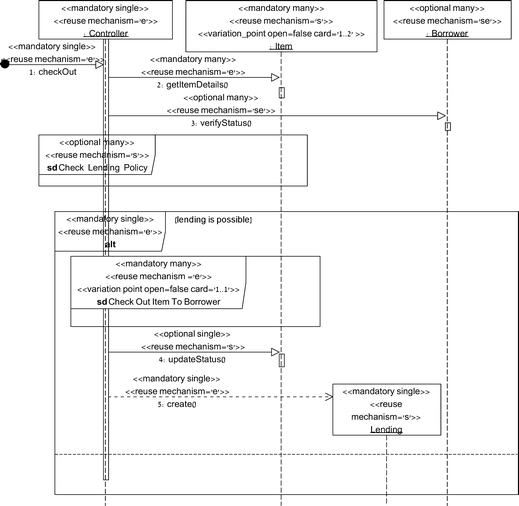
CICO model: the check out scenario
Fig. 18 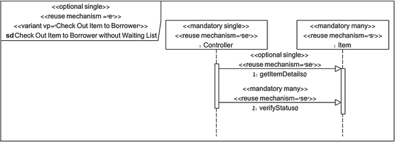
CICO model: check out without waiting list
Fig. 19 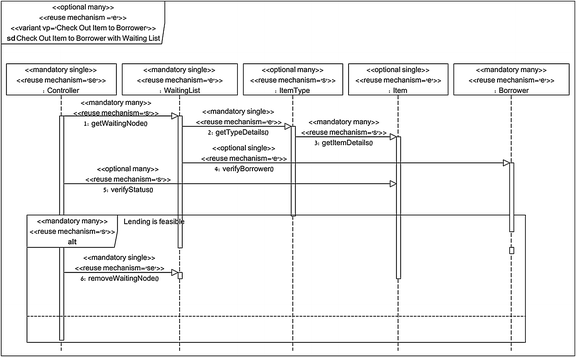
CICO model: check out with waiting list


Rights and permissions
About this article
Cite this article
Reinhartz-Berger, I., Sturm, A. Comprehensibility of UML-based software product line specifications. Empir Software Eng 19, 678–713 (2014). https://doi.org/10.1007/s10664-012-9234-8
Published:
Issue Date:
DOI: https://doi.org/10.1007/s10664-012-9234-8