
1 Introduction
Usually, humanoid walking gait can only roughly be distinguished between stable and unstable. The evaluation of humanoid walking stability is difficult to quantify in scales. The famous criteria, center of pressure (COP) (Sardain & Bessonnet, Reference Chevallereau, Grizzle and Shih2004; Picado et al., Reference Azad, Babič and Mistry2009) and zero moment point (ZMP) (Vukobratovic & Stepanenko, Reference Ferreira, Crisóstomo and Coimbra1972; Vukobratovic & Borovac, Reference Fu and Chen2004), only focus on deriving stable humanoid walking gaits. Fu and Chen (Reference Kim, Lee, Yoo and Kim2008) addressed the stable and robust walking gait based on sensory feedback control for stair climbing. Chevallereau et al. (Reference Lu, Silva, Zhang, Wang and Lopes2009) developed three feedback controllers to achieve an asymptotically stable, periodic and fast walking gait. To find good stability, Ferreira et al. (Reference Mu and Wu2009) experimented with human gait for the control of a biped robot.
Stability is a major criterion of humanoid robots in dynamic or static walking. The COP located at the bottom of the foot affects humanoid walking stability. Thus, the study of the COP region for which a humanoid robot remains stable is an interesting topic. In addition, impact effects extremely influence humanoid walking stability (Kim et al., Reference Sardain and Bessonnet2006; Mu & Wu, Reference Picado, Lau, Reis and Gestal2006). Some researchers designed special foot bottoms to reduce impact effects (Yamaguchi et al., Reference Vukobratovic and Borovac1995; Yamaguchi & Takanishi, Reference Vukobratovic and Stepanenko1996). This paper proposes the COP position be used to observe impact effects and determine how to reduce them. Thus, the stable COP regions improve the humanoid walking for a robust gait.
In recent years, using COP for humanoid walking becomes popular. Lu et al. (Reference Yamaguchi, Takanishi and Kato2012) developed the strategy to control COP position of single-legged robot for balancing. Azad et al. (Reference Yamamoto2014) studied the effect of hand contact force on the displacement of COP. Luo et al. (Reference Yamaguchi and Takanishi2011) proposed a walking pattern based on COP. Ferreira et al. (Reference Mu and Wu2009) made use of both a video camera to acquire image of a walking person and eight force sensors to acquire COP for the analysis of human walking stability. The acquired COP trajectory is applied to humanoid robot too. Yamamoto (Reference Luo, Li and Zhu2014) proposed the idea to control robot center of gravity by using COP. However, the stability of humanoid walking gaits is very sensitive on environment, especially on different floors. Thus, the methodologies to quickly construct a stable walking gait are necessary for the practical application of humanoid. To fast learn humanoid walking gait, there are many robot competitions, such as RoboCup (www.RoboCup.org) and FIRA (www.fira.net/main), to become popular international activities.
However, the humanoid should need different walking gaits for different movement objectives, such as fast walking, uneven floor walking, running and so on. Thus, to develop different kinds of walking gaits is the other challenge to humanoid robot research. The HuroCup (https://www.facebook.com/groups/hurocup/) organized for multiple events including nine events: sprint, penalty kick, obstacle run, lift and carry, weight lifting, basket ball, long jumping, united soccer, and marathon. Those nine events lead the study of humanoid walking gait to solve the problem of different movement objectives. The authors organized NKFUST humanoid robot team to participate HuroCup for many times, and to face this problem. In this paper, the experience of participating HuroCup is summarized as the idea of stable COP regions for the problem solution. The stable COP regions are used to evaluate and improve humanoid walking gaits. The stability margins of a walking COP trajectory with respect to the stable COP regions identify the stability of the walking gait. The experiment results demonstrate that the stable COP regions can get stable walking gaits quickly for different environment and different movement objectives.
This paper is organized as follows. Section 2 derives our empirical model of COP position. The COP position change during humanoid robot walking is simplified by the most influential joint rotation for modeling purposes. The most influential joint is derived in Section 3. In Section 4, actual experiments to identify the stable COP regions of a humanoid robot are presented. The stable COP regions used to evaluate and improve walking gaits are presented in Section 5. Finally, conclusions and further developments are presented in Section 6.
2 Center of pressure position calculation
COP positions can evaluate the stability in humanoid walking gaits. In this section, a way to measure COP is discussed in detail. Moreover, because the humanoid walking gait utilizes either single or double support phases, the COP discussion includes both phases.
ZMP and COP play a significant role for humanoid robot walking stability. Both of them control different dynamic phenomena (Sardain & Bessonnet, Reference Chevallereau, Grizzle and Shih2004). The former needs installed force torque sensors and the latter engages force sensors under the feet. Measuring COP ignores the affect of torque. Force under the feet during robot walking can be approximated by the vertical force reflected from the ground. The phenomena of more dynamics needed for ZMP during humanoid robot walking increases the complications of improving the walking gait. Hence, this study proposes to simplify the stability evaluation by using force sensors to measure the COP.
Humanoid walking gaits include single and double support phases. The COP measurement of double support phase when both feet contact the ground simultaneously is more complicated than that of single support phase. The following thus discusses the simple single support phase first. Figure 1 demonstrates a methodology to measure COP in single support phase, where force sensors are set by rectangular distribution. Let the lower left corner be the origin of the sensor coordinate system. Then four installed sensors are located at (X m , Y m ), for m=1, … , 4, where the forces measured from sensors are F zm (m=1, … , 4).
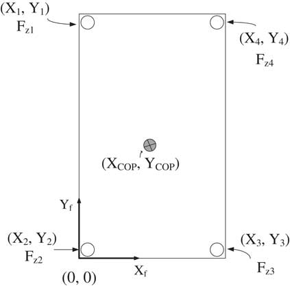
Figure 1 A methodology to measure center of pressure (COP)
Assume the position of COP located at (X COP, Y COP) in the sensor coordinate plane X f −Y f . The following Lemma indicates the COP position during the humanoid robot at single support phase (12).
Lemma 1. Let the force sensors be installed on the bottom of the foot as shown in Figure 1. Then the COP position is
 $$X_{{\rm COP}} {\, \equals \,}{{X_{1} F_{{Z1}} {\plus}X_{2} F_{{Z2}} {\plus}X_{3} F_{{Z3}} {\plus}X_{4} F_{{Z4}} } \over {F_{{Z1}} {\plus}F_{{Z2}} {\plus}F_{{Z3}} {\plus}F_{{Z4}} }}$$
 $$Y_{{\rm COP}} {\, \equals \,}{{Y_{1} F_{{Z1}} {\plus}Y_{2} F_{{Z2}} {\plus}Y_{3} F_{{Z3}} {\plus}Y_{4} F_{{Z4}} } \over {F_{{Z1}} {\plus}F_{{Z2}} {\plus}F_{{Z3}} {\plus}F_{{Z4}} }}$$
In the double support phase, it is possible for the COP position to move out of the area enclosed by four sensors on the same foot. That is why the COP calculation of double support phase is more complicated than that of single support phase. This study, therefore, proposes an approximate method as follows. Since the humanoid robot supports the body with two legs, the COP position under the two feet can be obtained. Figure 2 shows a humanoid in the double support phase in which P a and P b are the COP positions calculated by Equations (1) and (2) from left and right feet sensors, respectively. The COP position for the humanoid walking in the double support phase can be approximated by the following theory:
Theorem 1. Let the lower left corner be the origin of the sensor coordinate system. In a situation in which two feet touch the ground as shown in Figure 2, the COP position of the whole support area can be approximated as
 $$X_{{\rm COP}} {\, \equals \,}X_{a} {\plus}(X_{b} {\, \minus\,}X_{a} )\left( {{{\mathop{\sum}\limits_{m{\, \equals \,}1}^4 {\! F_{{bm}} } } \over {\mathop{\sum}\limits_{m{\, \equals \,}1}^4 {\! F_{{am}} } {\plus}\mathop{\sum}\limits_{m{\, \equals \,}1}^4 {\! F_{{bm}} } }}} \right),\,and$$
 $$Y_{{\rm COP}} {\, \equals \,}Y_{a} {\plus}(Y_{b} {\, \minus \,}Y_{a} )\left( {{{\mathop{\sum}\limits_{m{\, \equals \,}1}^4 {\! F_{{bm}} } } \over {\mathop{\sum}\limits_{m{\, \equals \,}1}^4 {\! F_{{am}} } {\plus}\mathop{\sum}\limits_{m{\, \equals \,}1}^4 {\! F_{{bm}} } }}} \right)$$
where F am and F bm (m=1, … , 0) are the force values captured from the left and right feet sensors. (X a , Y a )=P a and (X b , Y b )=P b are the left and right COP positions calculated from F am and F bm (m=1, … , 0), respectively.
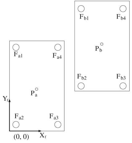
Figure 2 The Center of pressure positions of left and right feet during a double support phase
Proof. The proof provides an explanation of the approach used in
the equations. Let’s explain Equation (3) first. In the left support phase,
 $$\mathop{\sum}\limits_{m{\, \equals \,}1}^4 {\! F_{{bm}} } {\, \equals \,}0$$
. Hence, the second term of Equation (3) on the right hand side is 0. Equation (3) becomes
X
COP=X
a
that satisfies the COP position of the humanoid in the left support phase. On
the other hand,
$$\mathop{\sum}\limits_{m{\, \equals \,}1}^4 {\! F_{{bm}} } {\, \equals \,}0$$
. Hence, the second term of Equation (3) on the right hand side is 0. Equation (3) becomes
X
COP=X
a
that satisfies the COP position of the humanoid in the left support phase. On
the other hand,
 $$\mathop{\sum}\limits_{m{\, \equals \,}1}^4 {\! F_{{am}} } {\, \equals \,}0$$
during the humanoid robot in the right support phase. Equation (3) becomes
$$\mathop{\sum}\limits_{m{\, \equals \,}1}^4 {\! F_{{am}} } {\, \equals \,}0$$
during the humanoid robot in the right support phase. Equation (3) becomes
 $$X_{{\rm COP}} {\, \equals \,}X_{a} {\plus}(X_{b} {\minus}X_{a} ){\, \equals \,}X_{b} $$
Equation (5) shows that Equation (3) satisfied the definition of the humanoid robot in the right support phase too.
Because the double support phase connects the phases between left and right supports, it is reasonable to assume that the COP position moves from (X a , Y a ) to (X b , Y b ) during the humanoid walking in this phase. Therefore, the COP position satisfies
 $$X_{a} {\rm \,\lt\,}X_{{{\rm COP}}} {\rm \,\lt\,}X_{b} \,{\rm and}\,Y_{a} {\rm \,\lt\,}Y_{{{\rm COP}}} {\rm \,\lt\,}Y_{b}. $$
Let the COP positions be proportional to the measured force
values. Then
$$X_{a} {\rm \,\lt\,}X_{{{\rm COP}}} {\rm \,\lt\,}X_{b} \,{\rm and}\,Y_{a} {\rm \,\lt\,}Y_{{{\rm COP}}} {\rm \,\lt\,}Y_{b}. $$
Let the COP positions be proportional to the measured force
values. Then
 $$(X_{{\rm COP}} {\minus}X_{a} )\,\colon\,(X_{b} {\,\minus\,}X_{a} ){\, \equals \,}\mathop{\sum}\limits_{n{\, \equals \,}1}^4 {F_{{bm}} } \,\colon\,\mathop{\sum}\limits_{n{\, \equals \,}1}^4 {F_{{am}} } {\plus}\mathop{\sum}\limits_{n{\, \equals \,}1}^4 {F_{{bm}} } $$
Thus,
 $$(X_{{\rm COP}} {\,\minus\,}X_{a} ){\, \equals \,}{{(X_{b} {\minus}X_{a} )\mathop{\sum}\limits_{n{\, \equals \,}1}^4 {F_{{bm}} } } \over {\mathop{\sum}\limits_{n{\, \equals \,}1}^4 {F_{{am}} } {\plus}\mathop{\sum}\limits_{n{\, \equals \,}1}^4 {F_{{bm}} } }}$$
Moving X a to the right hand side of Equation (7) one can obtain Equation (3). Similarly, Equation (4) can be obtained.□
Exact COP position of the humanoid robot in the double support phase is calculated in Equations (3) and (4) from measured force sensor values. In the experiments during a walking gait, all the measured COP points are connected for a trajectory according to time sequence. The COP trajectory can be used to evaluate the stability of humanoid walking gaits according to stable COP regions.
3 The analysis of center of pressure influenced by joints
In this study, the COP positions of the humanoid during stable standing are measured by experiments for the evaluation of the walking gait stability. Humanoid robots are a multiple link platform. A COP position is simultaneously influenced by many joints which makes measuring experiments complicated. In this section, the dominant joint that influences COP is analyzed to simplify experiments.
In general, a humanoid robot has two joints at one ankle, one joint at one knee and three joints at one hip. Let the joint angles of its leg be θ i (i=1, … , 6) as shown in Figure 3. The rotation of θ 1 and θ 2 manipulates its ankle, θ 3 manipulates its knee, and θ 4, θ 5 and θ 6 manipulate its hip. Stable walking consists of the perfect matching of both feet from θ 1 to θ 6. Thus, they play a key role for the humanoid to walk. During the humanoid walking, the COP is the result of torque from the joint rotation to its body. Hence, the rotation torque is analyzed because it is the most influential joint affecting the COP. Based on the comparison of all joint torque, the analysis focuses on the dominant joint to simplify COP position experiments.
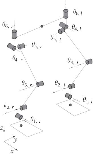
Figure 3 A kinematic model of a humanoid robot
A humanoid robot is usually separated into sagittal and frontal planes for analysis. The humanoid walking in the sagittal plane is the maneuvering in X−Z plane as shown in Figure 4. The rotation angles at ankle, knee and hip are pertaining to θ 2, θ 3 and θ 5, respectively. Therefore, the torque resulting in θ 2, θ 3 and θ 5 rotations for the humanoid body are compared to find the dominant joint.
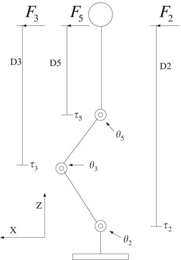
Figure 4 The joints and torque of the humanoid robot in sagittal plane
Let F i be the force delivered via the ith joint for the manipulation of humanoid body mass, and D i be the distance between humanoid body mass and ith joint as shown in Figure 4. Then the torque delivered by the ith joint for the humanoid body maneuvering is
 $$\tau _{i} {\rm {\, \equals \,}}F_{i} {\times}D_{i} $$
Let the joints in the sagittal plane steer the humanoid body with the same force values, that is, F 2=F 3=F 5. Then in Equation (8), τ 2>τ 3>τ 5 because of D 2>D 3>D 5. As a result, the ankle torque τ 2 has the most affect on the body’s stability. Thus in the next section, the COP position influenced by the ankle rotation angle is studied by experiments in the humanoid robot sagittal plane. The experiments include left and right ankles, τ 2,L and τ 2,R . The experiment results reveal the COP regions of the humanoid robot that remain stable in the standing position.
In the frontal plane, the humanoid robot maneuvers in the Y−Z plane. Consequently, the analysis aims at the rotation torque resulting from θ 1 and θ 4. θ 1 and θ 4 are where the angles of hip and ankle have been rotated to X axis. Similar to the analysis in the sagittal plane, τ 1 results in the most torque to the humanoid body. Thus, θ 1 is the dominant joint of the humanoid robot maneuvering in the frontal plane. The COP position related to θ 1 rotation was discovered by experiments for the stable COP regions.
4 Measure of stable center of pressure regions
In this section, the COP positions in which the humanoid robot stays on flat ground at a stable standing position models the stable region. The experiments formulate the relationship between the COP positions and the dominant joint angles. In the next section, the stable COP regions evaluate the stability margins of walking gaits to improve for robust stability.
Let the humanoid walking gait start at the double support phase using the left leg at the front, named phase A. During the forward walking, the humanoid body’s center of gravity needs to transfer onto its left foot for a left support phase named phase B. During phase B, the humanoid robot swings its right leg forward to land at the next body support location on the ground. Landing the right leg terminates phase B, and then starts the double support phase using right leg at the front, named phase C. In the phase C, the humanoid adjusts its four joints to support the body for stable standing. After stable standing, the humanoid robot lifts and then swings its left leg in a right support phase named phase D. After the left leg that was swung lands on the ground, the humanoid revisits phase A, the double support phase. Phases A, B, C and D consist of the humanoid walking gait using left leg at the front. If the humanoid robot wants to walk continuously, phases A, B, C and D sequentially operate for the next gait.
The experimental platform is a commercial humanoid robot, Bioloid, developed by ROBOTIS Company. Bioloid consists of 18 AX-12+servo motor. In this study, four force sensors are installed into each foot of the Bioloid to measure the COP positions, as shown in Figure 5. In addition, a field-programmable gate array board captures the force sensor values and sends them to a personal computer via RS-232. After the sensor data are collected in the personal computer, a proprietary program can filter out noise and calculate COP positions. The main benefit of the sensor data saved and accessed in the personal computer is to have enough memory for COP trajectories during the Bioloid walking.
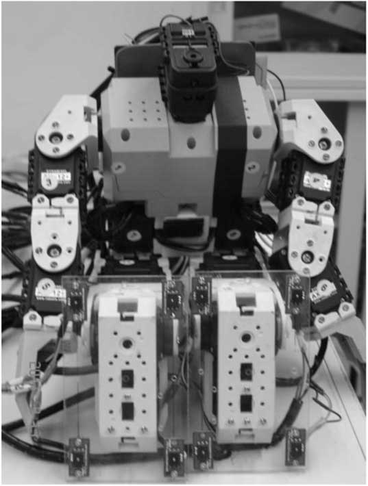
Figure 5 The experiment humanoid robot (eight force sensors (red color circuit board) under the bottom of both feet)
The following data models the stable COP regions of the humanoid robot through experiments divided into four phases. Since the double support phase requires the data from the single support phase, the experiments start with the single support phases (phases B and D).
4.1 Phase B: left leg support
At the conclusion of the left support phase, the ankle is the dominant joint. Thus, the experiments of this phase concentrate on the relationship between the ankle angles and the COP positions in the sensor coordinate plane X f −Y f . The relationships include the COP positions influenced by θ 1,L angle rotation to X axis and θ 2,L rotation to Y axis, respectively. Let the origin of a sensor coordinate plane X f −Y f be the left back corner of the humanoid foot support polygon. Thus, a new X f −Y f plane defined for every phase in the walking gait can easily describe the COP positions. Notice that the sensor coordinate plane X f −Y f is different from the humanoid coordinate plane X−Y. X f −Y f is equal to rotating X−Y to Z 90°.
In theory, the COP position moves on the X f axis in the X f −Y f plane while the Bioloid rotates θ 1,L in the frontal plane. Similarly, the θ 2,L rotation in the sagittal plane influences the COP position on the Y f axis. As a result, the experiments record X COP with respect to θ 1,L rotation, and Y COP with respect to θ 2,L rotation, respectively.
The first experiment rotates θ 1,L when the Bioloid is in the stable left support phase for X COP. In this experiment, the other joints θ 2,L and θ 1,R to θ 6,R in the frontal plane are fixed at normal angles. Let θ 1,L increase the angle from small to large. Then the COP positions in which the Bioloid can remain at a stable standing position during the left support phase are recorded. The experiment’s results are shown in Table 1. The stable COP positions for X COP range from 12.3625 to 35.4361 mm when θ 1,L rotates from 70.5 to 76.3°. Notice that the numbers inside the bracket in Table 1 are the motor position values. Similarly, Table 2 shows the experiment results of stable Y COP range. The Bioloid can remain in the stable standing position during X COP from 76 to 13.9361 mm.
Table 1 The stable X COP with respect to θ 1,L in phase B
Table 2 The stable Y COP with respect to θ 2,L in phase B

From Tables 1 and 2, the stable ranges of Y COP and X COP can be combined for the stable COP region as shown in Figure 6. Although only the dominant joint angle creates the stable COP region, the other joints influence the COP positions too. The most important thing in the result is only the stable COP region. Hence, a reasonable approach only uses the dominant joint angle rotation to model the location of the stable COP region.
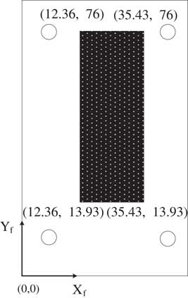
Figure 6 The stable center of pressure region for the Bioloid in the left support phase
4.2 Phase D: right leg support
From the analysis results in the previous section, the right ankle is the dominant joint to influence COP position in the right support phase. Therefore, the experiments in this phase focus on the relationship between right ankle joint angles and COP positions. In other words, while the Bioloid is in a stable standing position in the right support phase, the experiments record X COP and Y COP with respect to θ 1,R and θ 2,R , respectively.
The first experiment rotates θ 1,R for the stable X COP. Let the joint θ 2,R and θ 1,L to θ 6,L be fixed at normal angles in the frontal plane. Then rotating the θ 1,R angle from small to large, the search is made for the angle ranges of the Bioloid during the stable standing position in the right support phase. In this stable range, the relationship between θ 1,R and X COP is recorded in Table 3. As shown in Table 3, the stable angle range of θ 2,R is from 72 to 77.9°. Meanwhile the stable X COP changes from 9.7680 to 34.974 mm.
Table 3 The stable X COP with respect to θ 1,R in phase D
A similar experiment obtains the stable Y COP with respect to θ 2,R . Table 4 shows the results of the experiment. The Bioloid can maintain the stable standing position in the right support phase while θ 2,R changes from 76.1 to 87.7°. In this stable angle range, the Y COP changes from 76 to 21.7490 mm.
Table 4 The stable Y COP with respect to θ 2,R in phase D
The stable COP region for the Bioloid in the right support phase can be combined from Tables 3 and 4. The results reveal the range at which the Bioloid can stably stand in the right support phase by using COP in this region.
4.3 Phase A: double support using left leg at the front
In this phase, θ 2,R and θ 2,L rotate around Y axis (i. e. X f axis) on X−Z plane (the sagittal plane). While θ 2,R and θ 2,L are changing, the variation of Y COP is recorded in this experiment.
In this phase, two feet landing on the ground make the measure of the COP position complicated. Three key points are identified in the following. First, the COP position can be calculated by Equations (6) and (7) from Theorem 1. Second, the definition of a sensor coordinate plane for this phase is developed. The sensor coordinate plane X f −Y f must cover both feet like Figure 2. However, Figure 2 expresses the double support phase using right leg at the front. The origin point of X f −Y f is designed at the left back corner of the rectangular polygon consisting of both feet in this phase. Third, the dominant joint is found. In this phase, the dominant joints include left and right ankles. Thus, four joint angles, θ 1,R , θ 2,R , θ 1,L and θ 2,L , influence the COP position. However, the ideal manipulation of the double support phase using the left leg at the front transfers the humanoid robot center of gravity from right to left foot. Because the distance of left and right feet is large in Y f axis, but small in X f axis, the COP position change is large on Y COP, but small on X COP. Therefore, in the experiments, the X COP position influenced by θ 1,R and θ 1,L is ignored. The experiments only focus on Y COP with respect to the change of both θ 1,R and θ 1,L .
In the experiments of this phase we change the angle of θ 2,L and θ 2,R , while the others, θ 1, θ 3, θ 4 and θ 5 remain fixed at normal angles for the Bioloid in a stable standing posture. θ 2,L and θ 2,R must be changed simultaneously to search for the angle range of the Bioloid in a stable standing position. However, changing θ 2,L and θ 2,R simultaneously is complicated because of the endless choices and the mechanical constraint. A way to simplify the simultaneous change is to search for the stable Y COP from a stable standing posture. From this posture, the stable Y COP is found by turning the ankle or θ 2,L and θ 2,R in the clockwise direction and then the counterclockwise direction. In the search experiments, the stable Y COP positions are written with respect to θ 2,L and θ 2,R .
Table 5 provides the results of this experiment. As shown in Table 5, the stable Y COP positions range from 50.3761 to 104.2926 mm. From the experimental data, the X COP position change is small as in the previous analysis. Moreover, according to the gathered data, the Bioloid can stand stably when X COP is located within the stable region of single support phase. Therefore, the stable region of X COP in this phase makes use of the region in the left support phase, phase B.
Table 5 The stable Y COP in phase A
4.4 Phase C: double support using right leg at the front
In this phase, the only joints considered are the dominant ones or θ 2,R and θ 2,L according to the analysis in phase A. The experiments of this phase search for the stable Y COP position with respect to changes in θ 2,R and θ 2,L .
Let θ 1, θ 3, θ 4 and θ 5 be fixed at normal angles in the double support phase. Then, the stable Y COP positions are searched for by fine tuning θ 2,L and θ 2,R simultaneously until the Bioloid cannot stand in this phase. In the experiments, the stable Y COP positions are written with their corresponding θ 2,L and θ 2,R in Table 6. As shown in Table 6, the stable Y COP positions range from 37.5239 to 97.1218. In addition, the range of stable X COP positions can be found under the results in the right support phase, phase D.
Table 6 The stable X COP region in phase C
The experiments of phases A, B, C and D define the parameters of the stable COP regions. Figure 7 shows the stable COP regions. As shown in Figure 7, the COP positions inside the area of the red dash lines are stable. Knowing these regions is very useful to identify the walking gait stability. However, the design for the humanoid robot is a walking gait, not a posture. The walking gait results in a COP trajectory. Hence, the stability of a walking gait can be recognized by the distance that its COP trajectory moves out of the stable region margins. In the next section, the stability margins are utilized to adjust for better walking gaits.
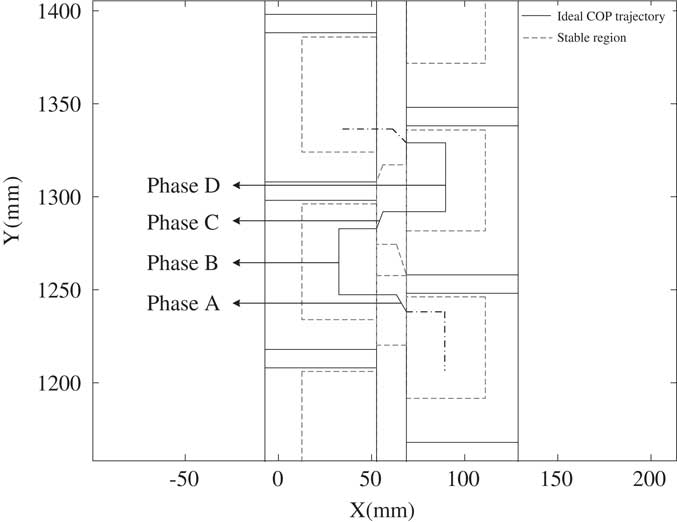
Figure 7 The stable center of pressure (COP) regions and the ideal COP trajectories for walking gait design
Theoretically, the COP position located at the center of stable region is the maximum stability margin. Such a walking gait is the best one in considering stability. Hence, Figure 7 also models an ideal COP trajectory consisted of black line segments in phases A, B, C and D. The four segments are the center lines of four stable COP regions. If stability is the only thing considered for the humanoid robot walking, the ideal COP trajectory is an excellent goal in adjusting the walking gait.
5 Robust walking gaits
In this section, the developed stable COP regions have defined the stability margins of walking gaits so that they can be engaged to adjust the walking gaits for better stability on flat ground. To demonstrate the robustness of the adjusted walking gaits, experiments of the humanoid walking gaits on different material terrains are also included.
Traditionally, the fine tuning of a humanoid walking gait was left to observation by researchers with a great deal of experience. However, the observation of stability status is difficult, and it took considerable training to gain the needed experience in order to efficiently fine tune. This traditional method wastes a considerable amount of time and is inefficient. Even a very experienced researcher cannot quantify how good a walking gait is, nor know how to improve a walking gait. Thus in this paper, the stable COP regions are proposed.
The Bioloid has a motion editor to design its walking gait. Appendix A shows a walking gait of the Bioloid to be examined for its COP trajectory. Note that the value in the table is motor position command ranged by [0 1023] for motor angle ranged by [0 360]. In Table A1, every command is sent by 150 ms, and every waling gait including four phases is run in 1.8 seconds. When the Bioloid robot is walking, the COP trajectory is capturing as Figure 8. The blue lines shown in Figure 8 are the COP trajectory of the walking gait. In addition, the black solid lines are the ideal COP trajectory. About the COP trajectory in Figure 8, we can see together with Figure 7 about four phases: phase A for double support (left leg at the front), phase B for left leg support, phase C for double support (right leg at the front) and phase D for right leg support. In Figure 8, the two circles point out bad COP trajectory in phases A and D, respectively. The COP trajectory in the circle of phase A is the switch of positions between left and right foot. Such results are consistent in the walking experiment and they all point to the fact that the Bioloid sways extremely from the left and right side even though phase A provides two feet to support its body. Moreover, the COP trajectory in the circle of phase D runs out of the stable COP region. The stable COP regions can be used to identify the stability margins of a walking gait.
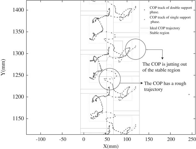
Figure 8 The center of pressure (COP) trajectory of a walking gait
Although the walking gait in Appendix A permits the Bioloid to walk, it is not good enough walking stability as shown in Figure 8. However, the two circles in Figure 8 are the only examples of COP outside of the margins of stability in the walking gait. All of the areas outside the margins of stability need to be identified for the modification of the walking gait. Thus, these places in the COP are distinguished by its phase and the motor position must be modified to find stability positions. For example, phase D identifies areas outside the stability margins, and three motor positions as shown in Table A1. Thus, the walking gait in that phase needs to be modified for more stable walking. When the COP trajectory moves out of the stable COP region, this implies that the motor positions in that particular phase are too large. Therefore, the second and third action of phase D should be modified with smaller motor positions. For example, in the second action of phase D, the motor position of θ 1,R is reduced by 10 (from 578 to 568). The other motor positions are also changed as the search for the stable positions.
Again we examine the Bioloid with the modified walking gait. Figure 9 shows the COP trajectory of this modified walking gait. As shown in Figure 9, the COP trajectory does not move out of the stable COP regions, and the walking gait stability extremely improves. The experiment of this walking gait is on the flat carpet ground. To examine its robustness, the walking gait experiments are conducted on tile and wooden ground as well. Figures 10 and 11 are the results of the experiment on these two terrains. As shown in Figure 10, the COP trajectory moves outside of the stable COP region because the hard tile results in more impact effect. As shown in Figure 11, the COP trajectory on wooden terrain does not move out of the stable COP regions, and the walking gait remains in the best stability zone. These extra two experiments demonstrate that although the walking gait is developed on carpet, it is still able to let the humanoid stably walk on tile and wooden ground. The walking gait developed by this research is robust on different terrains.
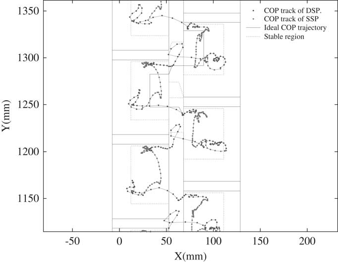
Figure 9 The center of pressure (COP) trajectory of a modified walking gait
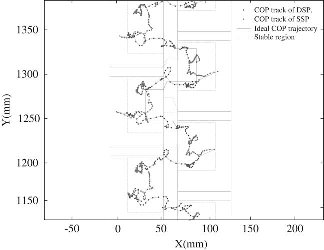
Figure 10 The center of pressure (COP) trajectory of the modified walking gait on the tile ground
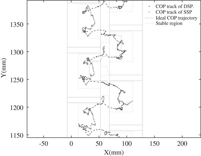
Figure 11 The center of pressure (COP) trajectory of the modified walking gait on wooden ground
6 Conclusions and further development
In this paper, the stability problem of humanoid walking gait is discussed using COP positions. The calculation of COP positions is derived by single support and double support phases. The measure of the COP position is divided into four phases sculpturing the COP regions of the humanoid during stable standing position, called the stable COP regions. The stable COP regions provide theoretical basis for this innovative idea of stability margins in the development of better humanoid walking gaits.
The stability margins of humanoid robot walking are proposed to evaluate and improve walking gaits. The stable COP regions are divided into four phases that can exactly identify the motor positions of poor stability in the walking gait. Thus, the walking gait can be improved by identifying the margins of its COP trajectory with respect to the stable COP regions. The improved walking gait is examined on three different terrains to demonstrate its robustness. The experiments conducted here demonstrate that the stability margins can be evaluated to improve the stability of a walking gait. The idea of the stable COP regions solves the problem of traditional methods that only identify a walking gait as stable or unstable. And, it becomes useful to adjust suitable walking gaits for multiple movement objectives. The walking gait adjustment based on stable COP regions is applied to HuroCup competition and to win many awards.
However, the stable COP regions have been researched in the experiments with the humanoid at static standing postures. Hence, the stable COP regions do not cover the motion dynamics of humanoid walking, and is a conservative approach to evaluate the stability of humanoid walking. In addition, the sensor, Inertia Motion Unit (IMU) is good to take the motion dynamics during humanoid walking. In the future, the stable regions covering the dynamic motion of humanoid walking and combining the signal with IMU would benefit for the study of better humanoid walking gaits.
Adult size more challenge in humanoid research. In the future, the research result will try to apply to the walking gait of adult-sized humanoid robot. To reduce the experiment difficulty of heavy and big humanoid body, a simulator is a good facility for the research of adult-sized humanoid walking gait. In the future, a simulator for adult-sized humanoid walking gait research are developed to construct a practically stable walking.
Acknowledgments
This research was supported by National Science Council, Taiwan, Republic of China under grant NSC 98-2622-E-327-018-CC2. In addition, the authors would like to appreciate Yun-Hsiang Sun to help parts of the experiments in this research.
Appendix A
Table A1 A walking gait for the Bioloid robot