Abstract
X-ray luminescence computed tomography (XLCT) is a hybrid molecular imaging modality combining the merits of both x-ray imaging (high spatial resolution) and optical imaging (high sensitivity to tracer nanophosphors). Narrow x-ray beam based XLCT imaging has shown promise for high spatial resolution imaging, but the slow acquisition speed limits its applications for in vivo imaging. We introduced a continuous scanning scheme to replace the selective excitation scheme to improve imaging speed in a previous study. Under the continuous scanning scheme, the main factor that limits the scanning speed is the data acquisition time at each interval position. In this work, we have used a gated photon counter (SR400, Stanford Research Systems) to replace the high-speed oscilloscope (MDO3104, Tektronix) to acquire measurement data. The gated photon counter only counts the photon peaks in each measurement interval, while the oscilloscope records the entire waveform including both background noise data and photon peak data. The photon counter records much less data without losing any relevant information, which makes it ideal for super-fast three-dimensional (3D) imaging. We have built prototype XLCT imaging systems of both types and performed both single target and multiple target phantom experiments in 3D. The results have verified the feasibility of our proposed photon counter based system and good 3D imaging capabilities of XLCT within a reasonable time, yielding a 14 times faster scanning time compared with the oscilloscope based XLCT system. Now, the total scan time is reduced to 27 seconds per transverse section.
Keywords: X-ray luminescence computed tomography, optical imaging, optical tomography, gated photon counter
1. INTRODUCTION
X-ray luminescence computed tomography (XLCT) was introduced in the past decade as a hybrid molecular imaging modality with great potentials for small-animal imaging by combining the high-spatial resolution of conventional x-ray imaging with the superb measurement sensitivity of optical imaging. Particularly, the narrow x-ray beam based XLCT has been shown to obtain very high spatial resolution, even at depths of several centimeters with good molecular sensitivity inside of turbid media [1, 2]. Briefly, a focused or collimated beam of x-ray photons is utilized to penetrate deeply through the specimen with minimal scatter. The x-ray excitable contrast agents within the path of the x-ray beam will absorb the x-ray energy and emit optical photons. Some emitted optical photons can propagate to object surface to be measured by sensitive optical detectors such as an electron multiplying charge-coupled device (EMCCD) camera or photomultiplier tube (PMT) for XLCT image reconstruction. The first demonstration of XLCT imaging was reported by Pratx et al. using a selective excitation scanning scheme, much like first generation x-ray CT scanners, and demonstrated the potentials of this imaging method [3, 4]. We have shown that by using a focused beam of x-rays as the excitation source for performing XLCT, orders of magnitude of better sensitivity can be achieved due to higher flux and efficient use of x-ray photons compared with the collimation-based method. In addition, higher measurement sensitivity can also be obtained by using PMTs as the optical detector compared with the EMCCD cameras [5]. Furthermore, we have showed that the scan time could be improved by introducing a continuous scanning scheme where the x-ray beam moves across the object in a single continuous motion and a set of data is acquired at predefined intervals [6]. Here, we have reported that the photon counter collects and transfers XLCT measurement data much faster than the oscilloscope. To further reduce the data acquisition time, we have used a gated photon counter to replace the high-speed oscilloscope in the XLCT imaging system. We have performed phantom experiments to verify the performance.
2. METHODS
2.1. XLCT experimental system set-up
Fig. 1 shows a photograph of the proposed imaging system in our laboratory. This imaging system is an upgraded version of the focused x-ray beam based XLCT imaging system previously described in [6]. In summary, an x-ray tube with a fixed polycapillary lens (X-Beam Powerflux [Mo anode], XOS) generates x-rays with a maximum energy of 50 kVp and tube current of 1.0 mA and are focused to an approximate focal spot size of 100 μm (focal distance: 44.5 mm). The imaged object is placed on a stage that within the focal spot of the x-ray beam and is fixed on top of a rotation stage (RT-3, Newmark Systems Inc.) mounted to a motorized vertical lift stage (VS-50, Newmark Systems Inc.) and linear stage (NLE-100, Newmark Systems Inc.) for rotating and translating the object at various depths. During the XLCT scans, emitted optical photons from our imaged object that propagate to the surface are collected using a single optical fiber cable (labeled Fiber 1) and delivered to a fan-cooled PMT (H7422-50). The signal from the PMT is then amplified using a broadband amplifier (SR455A, Stanford Research Systems) with a gain of 125 and then filtered with a low-pass filter (BLP-10.7+, fc = 11 MHz, Mini-Circuits) to reduce high-frequency noise. This signal is collected by the high-speed oscilloscope via Ethernet cable [6] and by the gated photon counter via IEEE-488 cable [7]. The entire imaging system up to the PMTs are placed inside of a light-tight and radiation shielding cabinet and controlled with a lab computer.
Figure 1.

Photograph of the imaging system
2.2. Phantom experimental set-up
Both single target and multi targets experiments were performed in our system. Fig. 2 shows the schematic of our phantom design. Cylindrical phantoms composed of 1% intralipid, 2% agar, and water with a diameter of 12 mm and height of 20 mm were made at our lab. For the single target experiments, one glass capillary tube target (outer diameter: 0.9 mm; inner diameter: 0.5 mm, Chang Bioscience) was filled with a solution of Gd2O2S:Eu3+ (GOS:Eu) (UKL63/UF-R1, Phosphor Techn. Ltd.) at a centration of 10 mg/mL. The target was embedded vertically in the background phantom. For the multi targets experiments, glass capillary tube targets (outer diameter: 0.8 mm; inner diameter: 0.4 mm, Drummond Scientific) were filled with the same GOS:Eu particle solution. For the parallel targe case, the two parallel capillary targets were obliquely (30 degrees from vertical surface) embedded in the background phantom as shown in Fig. 2b. For the centrosymmetric case, the two targets were also obliquely (30 degrees from vertical surface) in the background phantom and the two targets were centrosymmetric. For the single target XLCT experiment, the phantom was first scanned by the oscilloscope-based XLCT imaging system and then scanned by the photon-counter-based XLCT imaging system. For the two multi targets experiments, the phantoms were only scanned by the photon-counter-based XLCT imaging system. During all the experiments, all the experimental parameters were the same. The x-ray tube was operated at 30 kVp and 0.5 mA. The measurements were acquired at 6 angular projections with an angular step of 30 degrees. For each angular projection, the linear stage scanned in a continuous motion for 12 mm in which the measurement data were acquired every 0.1 mm. For each acquisition, the oscilloscope acquired all the photon peaks in a time of 4 ms. For the single target experiment, the photon counter acquired the photon peaks in a measurement time of 4 ms, 10 ms, and 40 ms for each acquisition step in the three different scans, respectively. For the multi target experiments, the photon counter acquired the photon peaks in a measurement time of 10 ms for each acquisition. After the data acquisition of all 6 angular projections for a transverse section was completed, the phantom was moved vertically by 0.1 mm so that the next transverse section scan was performed. In the single target experiment, we took measurements at 4 transverse sections at the scan depth of 5, 5.1, 5.2, and 5.3 mm, respectively. In the multi targets experiments, we took measurements at 10 transverse slices at 10 different scan depths with a step size of 0.1 mm. After the XLCT scans, the phantoms were placed inside of our microCT scanner to perform the microCT scan with 180 projections at a step size of 2 degrees. The microCT images were reconstructed in MATLAB using a filtered back-projection algorithm with a Shepp-Logan filter. For XLCT imaging, image reconstruction is similar to fluorescence molecular tomography (FMT) [10]. Images were reconstructed using an optical photon propagation model (radiative transport equation) inside turbid media which also included information such as the x-ray beam’s size and location as anatomical priors. We used the L1 regularized majorization-minimization algorithm. Details of the algorithm are described in [9–12].
Figure 2.
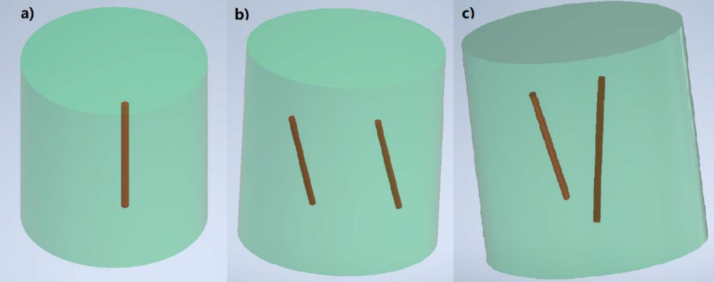
Phantom design: single target (a), parallel targets (b) and centrosymmetric targets (c).
3. RESULTS
XLCT Reconstructed images from the four single target experiments are shown below in Fig. 3, Fig. 4, Fig. 5 and Fig. 6 where scanning depths are (a) 5 mm, (b) 5.1 mm, (c) 5.2 mm, and (d) 5.3 mm, respectively. The green circles indicate the ground truth obtained from the microCT images. For all 16 scanned sections from the four experiments, we can see that the targets have been successfully resolved and are reconstructed at the correct locations. For the oscilloscope-based experiment as shown in Fig. 3, the DICE similarity coefficients are calculated to be 88.1, 89.7, 89.3, and 91.3 % for scan depths of 5, 5.1, 5.2, and 5.3 mm, respectively. For the photon-counter-based experiments, the DICE are calculated to be 89.0, 84.9, 84.3 and 90.3 % for scan depths of 5, 5.1, 5.2, and 5.3 mm with the data acquisition time of 4 ms per step (as shown in Fig. 4), 89.2, 90.0, 88.8 and 90.6% for scan depths of 5, 5.1, 5.2, and 5.3 mm with the data acquisition time of 10 ms per step (as shown in Fig. 5), and 89.8, 90.0, 91.1 and 90.8% for scan depths of 5, 5.1, 5.2, and 5.3 mm with the data acquisition time of 40 ms per step (as shown in Fig. 6), respectively. There is no noticeable difference in terms of the DICE coefficients between the oscilloscope based XLCT images and the photon counter based images. The scan depth should have no effects in the XLCT imaging performance too because we measured the emitted photon on the side surface. However, we see that more measurement times with photon counter result in slightly better DICE coefficients, which is reasonable because more measurement times give more photon counts per measurement interval.
Figure 3.
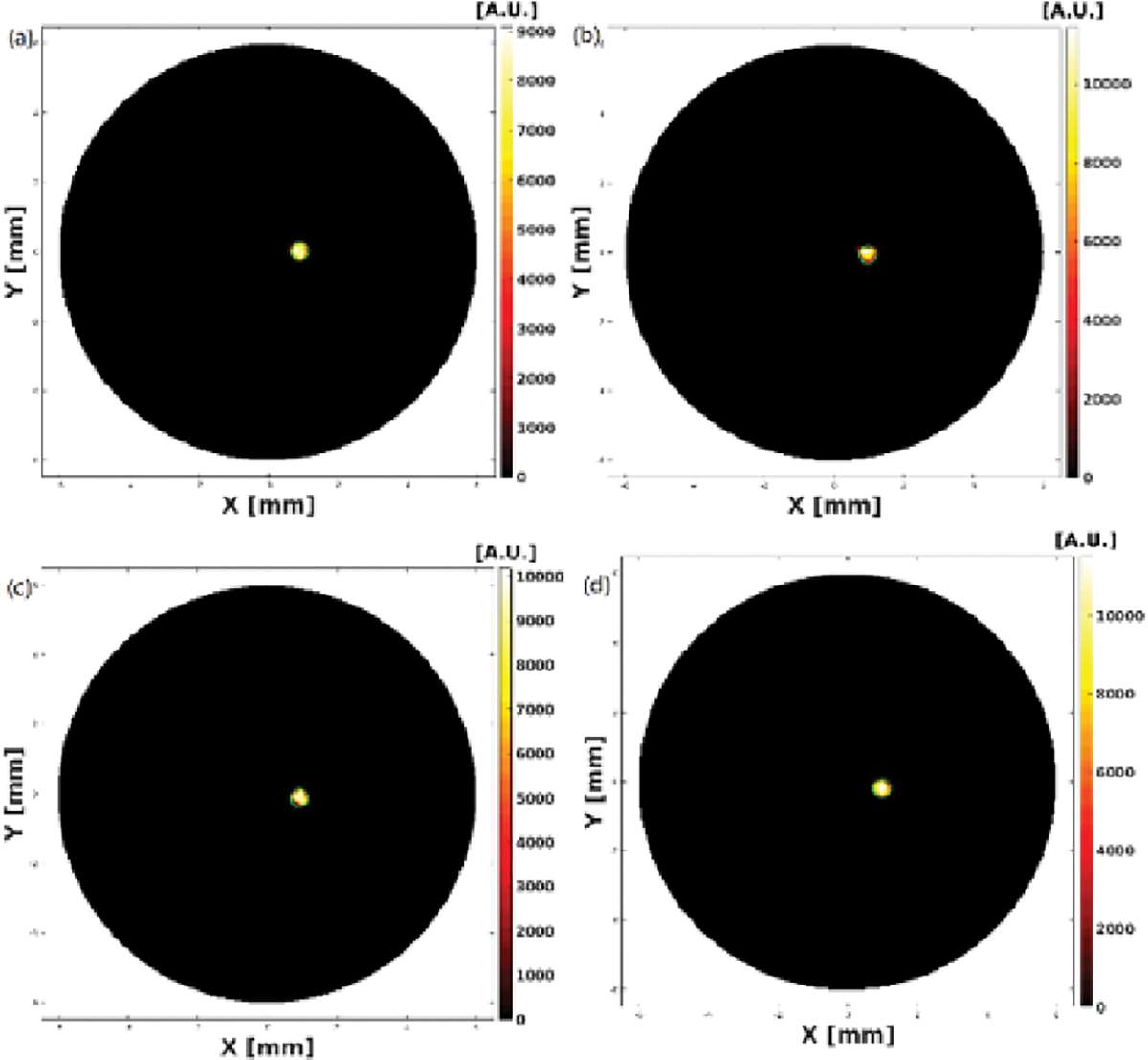
Reconstructed XLCT images from the oscilloscope based XLCT imaging system.
Figure 4.
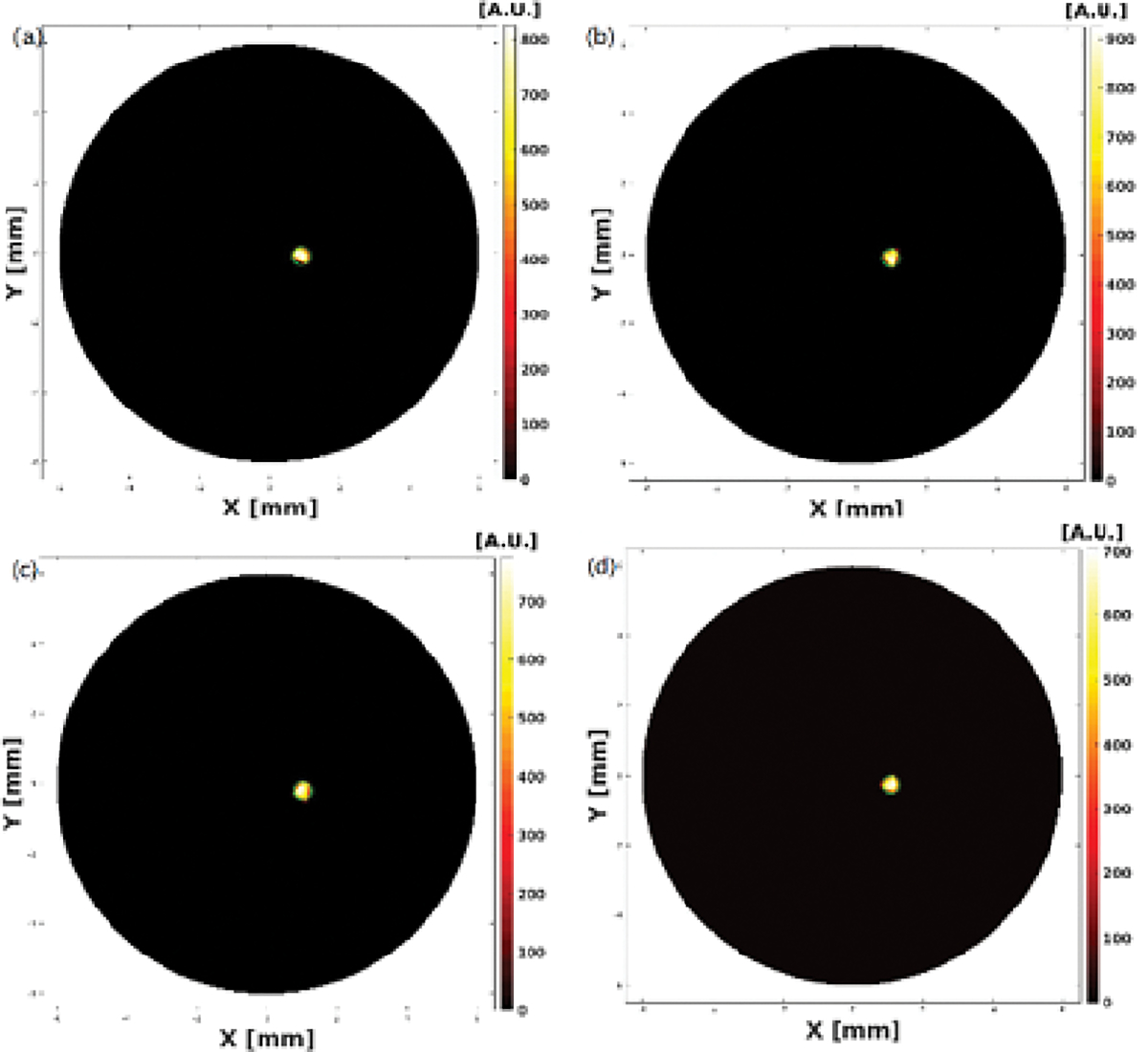
Reconstructed XLCT images from photon counter based XLCT imaging system with a data acquisition time of 4ms per step.
Figure 5.
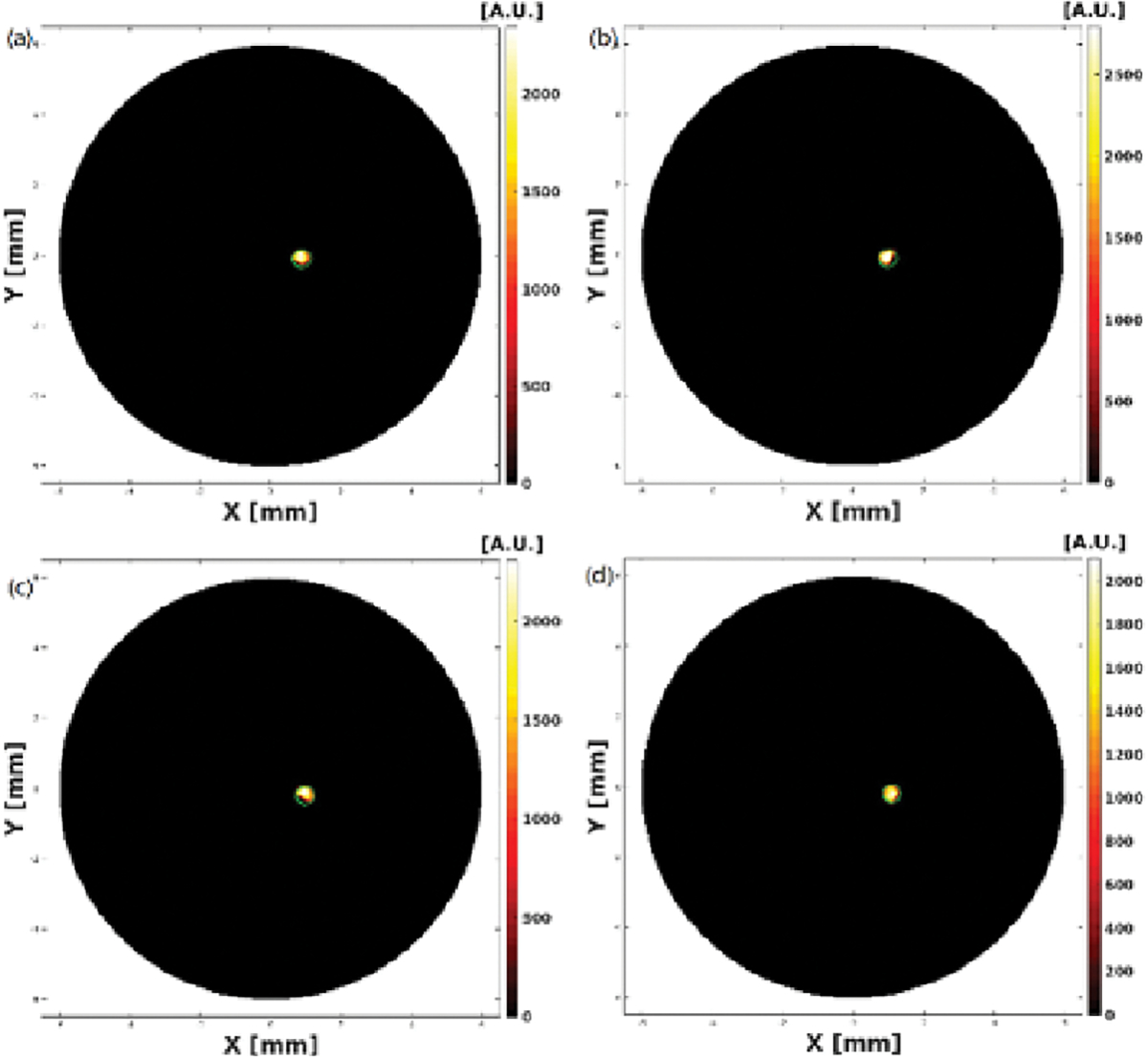
Reconstructed XLCT images from photon counter based XLCT imaging system with a data acquisition time of 10ms per step.
Figure 6.
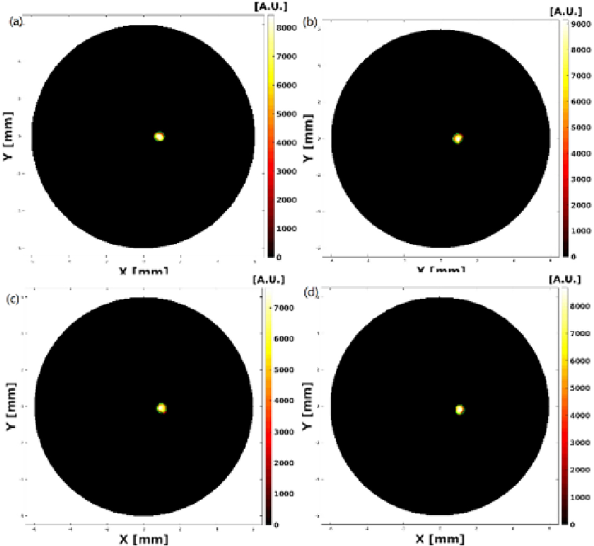
Reconstructed XLCT images from photon counter based XLCT imaging system with a data acquisition time of 40ms per step.
Table 1 shows the comparison of data acquisition time (including data save and transfer time), translation speed of the linear stage and total scan time between among the four experiments. We can see the data acquisition time of the oscilloscope (360 to 400ms) is much longer than that of photon counter (11 to 15ms). The proposed photon-counter-based super-fast imaging system (27 secs) is dramatically faster than the oscilloscope-based imaging system (373 secs)
Table 1.
data acquisition time, linear scan translation speed and total scan time with Oscilloscope and with Photon counter
| Experiment Settings | Data acquisition time (and transfer time) | Linear scan speed | Total time for 1 projection (120 steps) | Total time for 1 transverse section (6 projections) | Total time for all 4 sections |
|---|---|---|---|---|---|
| Oscilloscope 4ms | 360 to 400 ms | 0.2 mm/s | 60 seconds | 373 seconds | 1495 seconds |
| Photon counter 4ms | 11 to 15 ms | 5 mm/s | 2.6 seconds | 27 seconds | 113 seconds |
| Photon counter 10ms | 17 to 21 ms | 4 mm/s | 3.4 seconds | 32 seconds | 128 seconds |
| Photon counter 40ms | 47 to 50 ms | 1.8 mm/s | 6.9 seconds | 53 seconds | 216 seconds |
The reconstructed XLCT images from the two multi target experiments are shown in Figs. 7–10. For the parallel target case, Figs. 7 and 8 plot the reconstructed XLCT transverse sections at depths at 5 mm (7a), 5.1 mm (7b), 5.2 mm (7c), 5.3 (7d), 5.4 (7e), 5.5 mm (8a), 5.6 mm (8b), 5.7 mm (8c), 5.8 mm (8d), and 5.9 mm (8e), respectively. For the centrosymmetric target case, Figs. 9 and 10 plot plot the reconstructed XLCT transverse sections at depths at 5 mm (9a), 5.1 mm (9b), 5.2 mm (9c), 5.3 (9d), 5.4 (9e), 5.5 mm (10a), 5.6 mm (10b), 5.7 mm (10c), 5.8 mm (10d), and 5.9 mm (10e), respectively. For both multiple target cases, we can see that both targets have been successfully reconstructed. For the parallel target experiment, the DICE similarity coefficients are calculated to be 75.3%, 69.9%, 70.8%, 71.6%, 73.3%, 75.7%, 80.4%, 74.5%, 86.6% and 75.1 % for scan depths from 5 mm to 5.9 mm. For the centrosymmetric target experiment, the DICE similarity coefficients are calculated to be 81.8%, 79.5%, 80.3%, 83.3%, 74.8%, 87.3%, 70.8%, 81.8%, 84.4% and 73.6 % for scan depths from 5 mm to 5.9 mm. In particular, for both multiple target cases, we can observe the position changes of the target at different depths as we expected, which indicates that a good 3D imaging capability of our XLCT imaging system. In both multi targets experiments, the photon counter was set to collect photon peaks at a measurement time of 10 ms per acquisition or per linear scan step. The total scan time of measurements at ten transverse sections is 314 seconds.
Figure 7.
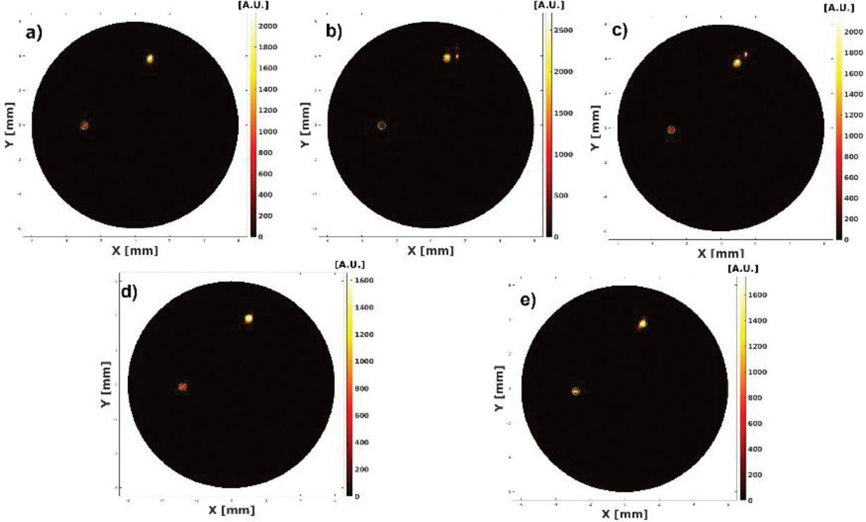
Reconstructed XLCT images from the parallel targets experiment at scanning depths of 5 (a), 5.1 (b), 5.2 (c), 5.3 (d), and 5.4 mm (e).
Figure 10.
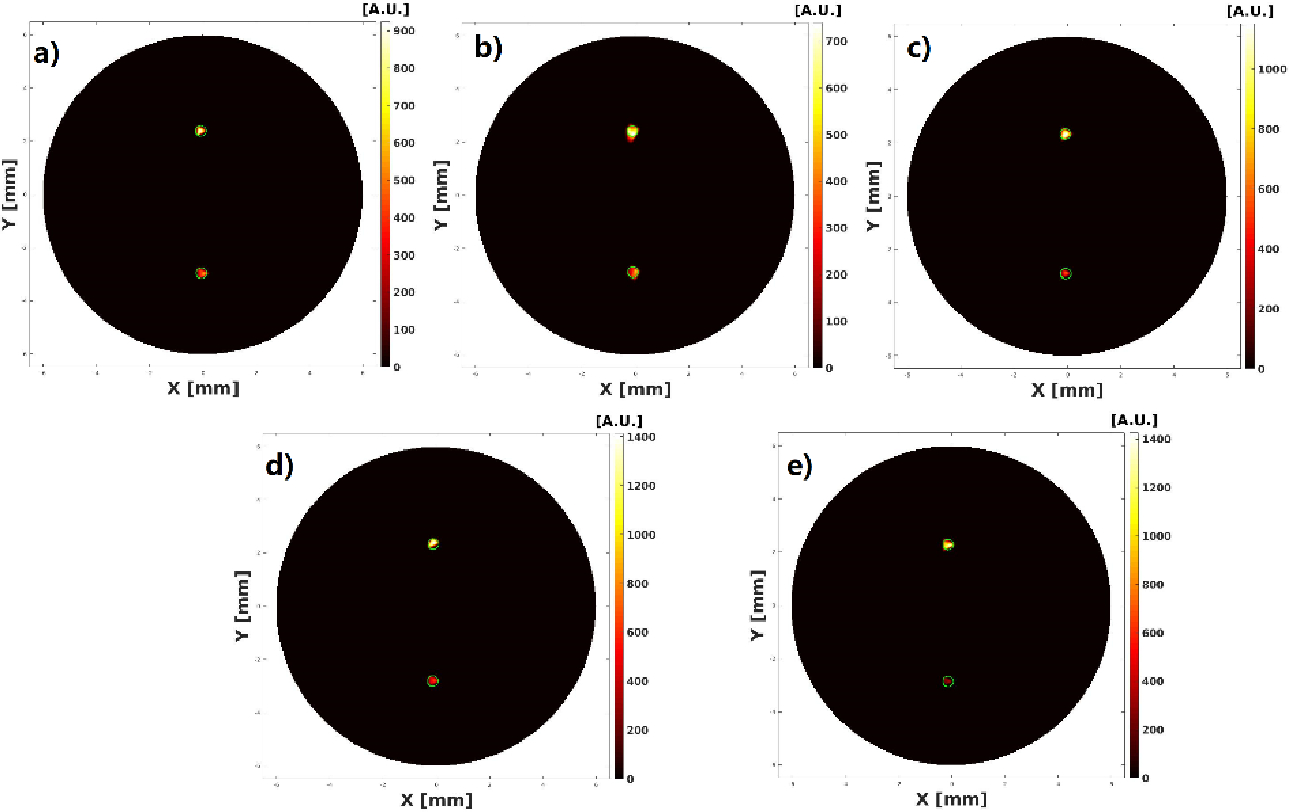
Reconstructed XLCT images from the centrosymmetric targets experiment with scan depths of 5.5 (a), 5.6 (b), 5.7 (c), 5.8 (d), 5.9 (e) mm
Figure 8.
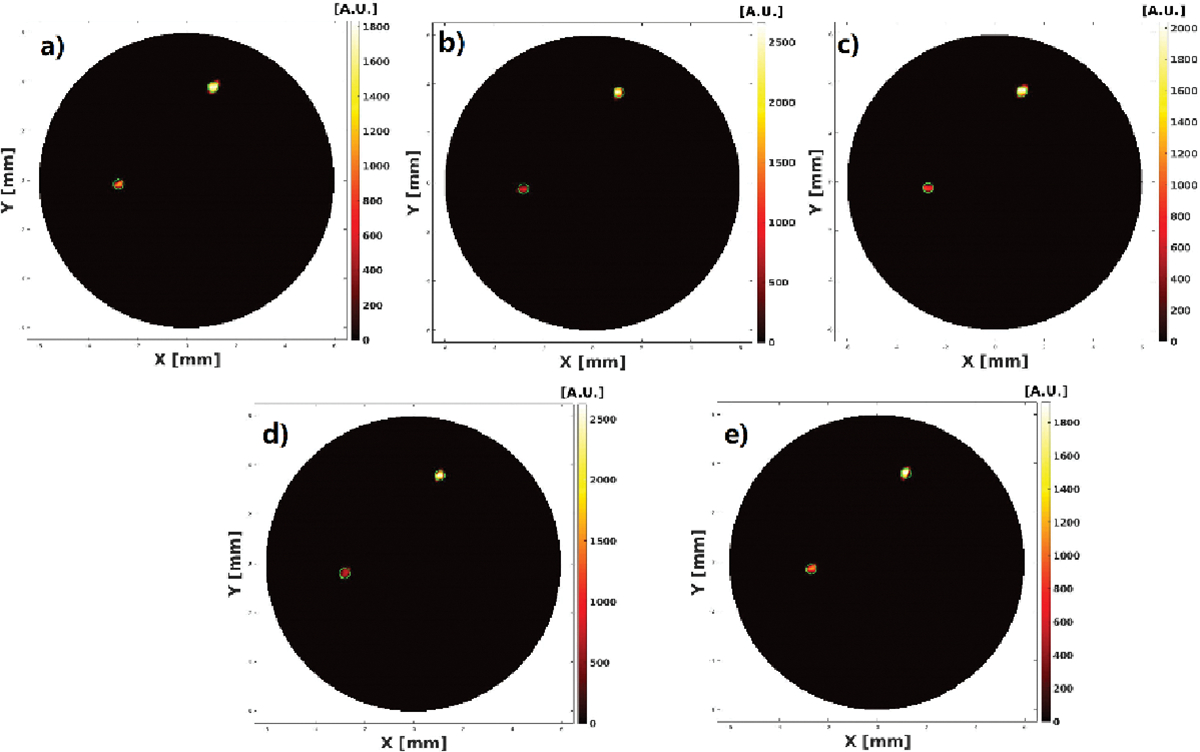
Reconstructed XLCT images from the parallel targets experiment at scan depths of 5.5 (a), 5.6 (b), 5.7 (c), 5.8 (d), and 5.9 (e) mm.
Figure 9.
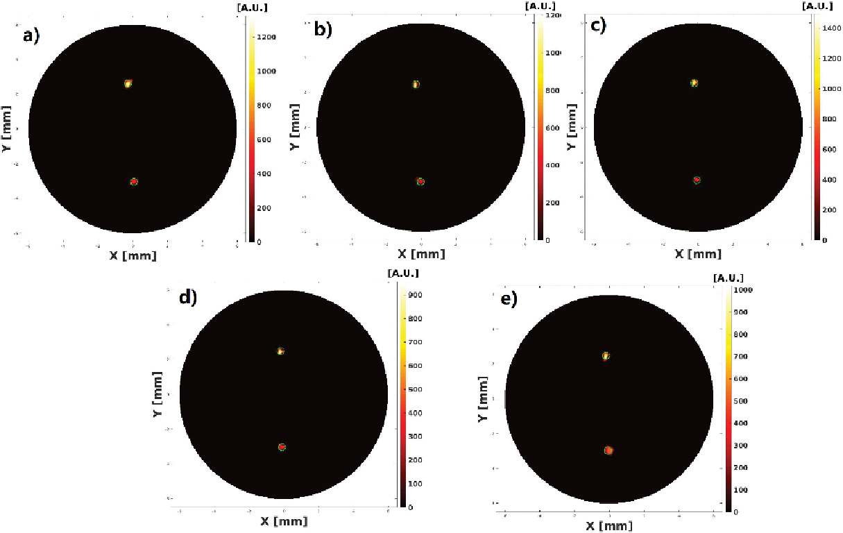
Reconstructed XLCT images from the centrosymmetric target experiment at scan depths of 5 (a), 5.1 (b), 5.2 (c), 5.3(d), and 5.4 (e) mm.
4. CONCLUSIONS
In this work, we have proposed and investigated a super-fast 3D XLCT imaging system using photon counter and the continuous scanning strategy to improve the imaging time. We were able to take measurements for each transverse section (with 6 angular projections) in 27 secs (15.4s scan time and 11.6s rotary time) including all stage movements using the photon-counter-based imaging system. Compared with 373 secs (361.4s scan time and 11.6s rotary time) using the oscilloscope-based imaging system, it’s approximately 23 times reduction in scan time and 14 times reduction in total time. Furthermore, we can achieve good DICE similarity coefficients for both single target and multi target XLCT experiments. Our multiple target XLCT imaging indicates the good 3D XLCT imaging capabilities within a reasonable time of 5 mins and 14s for a 10-slice scan. In future studies, we will investigate other scanning schemes to further reduce the scan time. We will also use the machine learning algorithms for better XLCT reconstruction and will apply the bright nanoparticle to save the measurement time further [13].
ACKNOWLEDGMENTS
This work was funded by the NIH National Institute of Biomedical Imaging and Bioengineering (NIBIB) [R01EB026646].
References
- [1].Lun MC and Li C, “High-resolution x-ray luminescence computed tomogra phy,” Proc. of SPIE 11317, Medical Imaging 2020: Biomedical Applications in Molecular, Structural, and Functional Imaging; 11317D (2020). [Google Scholar]
- [2].Lun MC, Zhang W, and Li C, “Sensitivity study of x-ray luminescence computed tomography,” Appl. Opt. 56 (11), 3010–9 (2017). [DOI] [PMC free article] [PubMed] [Google Scholar]
- [3].Pratx G, Carpenter CM, Sun C, Rao R, and Xing L, “Tomographic molecular imaging of x-ray excitable nanoparticles,” Opt. Lett. 35, 3345–3347 (2010). [DOI] [PubMed] [Google Scholar]
- [4].Pratx G, Carpenter CM, Sun C, and Xing L, “X-ray Luminescence Computed Tomography via Selective Excitation: A Feasibility Study,” IEEE Trans. Med. Imag. 29 (12), 1992–1999 (2010). [DOI] [PubMed] [Google Scholar]
- [5].Zhang W, Lun MC, Nguyen A, and Li C, “A focused x-ray beam based x-ray luminescence computed tomography,” J. of Biomed. Opt. 22 (11), 116004 (2017). [DOI] [PMC free article] [PubMed] [Google Scholar]
- [6].Lun MC, Fang Y and Li C, “Focused X-ray Luminescence Computed Tomography using a Continuous Scanning Scheme,” bioRxiv 2021.02.04.429805. [Google Scholar]
- [7].Jones Eric D., Preppernau Bryan L., and Matey James R., Editor Department, “Catching the Right Bus V: A Beginners’ Guide to Programming the IEEE-488 Bus”, Computers in Physics 9, 140–147 (1995) [Google Scholar]
- [8].Li C, Mitchell GS, Dutta J, Ahn S, Leahy RM, and Cherry SR, “A three-dimensional multispectral fluorescence optical tomography imaging system for small-animals based on a conical mirror design,” Opt. Expr. 17 (9), 7571–7585 (2009). [DOI] [PMC free article] [PubMed] [Google Scholar]
- [9].Zhu D, Zhao Y, Baikejiang R, Yuan Z, and Li C, “Comparison of regularization methods in fluorescence molecular tomography”, Photonics, 1, 95–109 (2014). [Google Scholar]
- [10].Zhu D and Li C, “Nonconvex regularizations in fluorescence molecular tomography for sparsity enhancement,” Phys. Med. Biol. 59, 2901–2912 (2014). [DOI] [PubMed] [Google Scholar]
- [11].Zhu D and Li C, “Nonuniform update for sparse target recovery in fluorescence molecular tomography accelerated by ordered subsets,” Biomed. Opt. Express 5, 4249–4259 (2014). [DOI] [PMC free article] [PubMed] [Google Scholar]
- [12].Zhu D and Li C, “Accelerated image reconstruction in fluorescence molecular tomography using a non-uniform updating scheme with momentum and ordered subsets methods,” J. Biomed. Opt. 21, 016004 (2016). [DOI] [PubMed] [Google Scholar]
- [13].Lun MC, Cong WX, Arifuzzaman M, Ranasinghe M, Bhattacharya S, Anker JN, Wang G, Li CQ, “Focused x-ray luminescence imaging system for small animals based on a rotary gantry”, Journal of Biomedical Optics, 26(3), 036004 (2021). [DOI] [PMC free article] [PubMed] [Google Scholar]


